
Immediate response
After a collision, preserve the KUKA robot, tooling, workpiece, and surrounding cell in their post-event condition until the available evidence has been recorded. Do not reset faults, jog the robot, remove the tool, clear the workpiece, alter mastering data, or release the equipment for production merely to see whether it will run. First place the cell in a controlled condition under the site's approved isolation and safeguarding procedures. Record any actions already taken after the event, because they may have changed the original evidence.
This approach does not identify a failed component by itself. It creates a reliable starting point for kuka robot repair assessment and helps an internal specialist or external repair provider distinguish collision consequences from pre-existing conditions, tooling problems, process interference, or incomplete operating information.
Define the equipment and event
Record the robot identification shown on its nameplate, the controller identification, the installed tool, and any external axes or positioners involved. Confirm the exact robot and controller variants against the applicable manuals before using model-specific instructions. The scope here is KUKA industrial robots of otherwise unspecified model; it does not establish procedures, limits, alarm meanings, or parts compatibility for a particular system.
Build a concise event timeline. Include the date and time, production mode, active job or operation, workpiece type, cycle stage, commanded direction of travel if known, and the first observed contact point. State whether the robot stopped immediately, remained loaded against an obstruction, dropped or retained the workpiece, or was moved afterward. Identify who observed the event and separate direct observations from later assumptions.
Capture the complete robot visually
Take wide photographs showing the entire robot, base, work envelope, guarding, tooling, workpiece, fixtures, and collision object. Photograph from several fixed viewpoints before anything is repositioned. Then capture closer views of every axis area, arm casting, cover, dress package, flange, tool mounting interface, hoses, cables, connectors, brackets, fasteners, and external equipment near the contact zone.
Include images that show orientation and scale without obscuring the damage. Record visible gaps, shifted witness marks, cracked or displaced covers, loose hardware, fluid residue, abrasion, deformation, cable pinching, damaged conduit, and tool or fixture displacement. A mark near an axis does not prove internal gearbox, bearing, motor, brake, or feedback damage. Conversely, an undamaged exterior does not rule out hidden mechanical or electrical effects.
Preserve controller and operating evidence
Photograph or transcribe the displayed messages exactly as presented, including their sequence and timestamps when available. Record the operating mode, program location, axis positions displayed by the system, override setting, and whether drives were enabled or disabled when the evidence was captured. Preserve available logs and backups through the equipment-specific procedure and according to site controls. Do not assign an alarm meaning unless it has been confirmed in the documentation applicable to that controller and software configuration.
Document the last known successful cycle. Record when it occurred, whether it used the same program, tool, payload, fixture, workpiece, and operating mode, and whether any unusual sound, vibration, path deviation, dress-package contact, or process variation had been noticed beforehand. This establishes a comparison point, but it does not prove that every robot subsystem was healthy immediately before impact.
Tool, payload, and process context
Record the installed tool identity, attached process equipment, workpiece condition, and the payload data believed to be active. Note any recent tool change, maintenance activity, fixture adjustment, program edit, production change, collision recovery, or payload update. Preserve relevant drawings, setup sheets, backup files, and change records.
A displaced fixture or damaged tool may indicate that the collision originated outside the robot. Incorrect or uncertain payload information may justify reviewing configuration and application setup, but it does not by itself establish the cause of the collision or prove mechanical damage. Similarly, visible cable damage supports inspection of the affected routing and circuits; it does not establish that the cable caused the event.
Reasoned diagnostic branches
If the contact geometry, tool position, and fixture evidence agree with the recorded program stage, assessment can concentrate on the impacted mechanical interfaces and the conditions that placed the robot there. This establishes a credible event sequence, not the internal condition of an axis.
If the physical position conflicts with the reported cycle stage, preserve that discrepancy. Possible branches include an incomplete timeline, movement after the stop, a different active program or frame, changed tooling, or an external process action. None should be selected without supporting records.
If damage appears limited to tooling or a fixture, the robot still requires checks appropriate to the transferred collision load. If robot covers, castings, flange interfaces, dress components, or base attachments show movement or damage, the affected areas require competent inspection before motion. If no damage is visible, hidden displacement, loss of calibration, or internal damage remains possible and must not be excluded solely from photographs.
Conditions for repair assessment
Release the equipment for repair assessment only when the identity and configuration are confirmed, the evidence package is complete, hazardous stored energy and suspended loads are controlled, and the robot is accessible under the site's approved safety process. The assessor should receive the timeline, original photographs, message records, backups, tool and payload context, maintenance history relevant to the event, and a list of actions taken after the collision.
Any inspection requiring covers to be removed, loads to be supported, or axes to be moved must follow the applicable robot manual and site procedure. Motion observation, where justified, requires competent staff, restored safeguards, an equipment-specific recovery method, and a controlled area. Do not repeatedly reproduce the collision or use blind parameter changes as a diagnostic method.
Verification before return to production
Verification must be based on the confirmed robot model, controller, application, and repair scope. It should confirm that identified damage has been addressed, disturbed interfaces are correctly restored, tooling and payload information are appropriate, required calibration or mastering checks have been completed, safeguards function as intended, and cables and process lines remain clear throughout the approved motion envelope.
A controlled functional check should begin under the equipment-specific procedure and progress only when each preceding result is acceptable. Compare the repaired system with the preserved last successful cycle, approved reference data, and process requirements. Successful motion alone does not prove full mechanical integrity, path accuracy, process quality, or safe production readiness. Final release should document the checks performed, their results, unresolved limitations, and the person authorized by the site to return the cell to service.
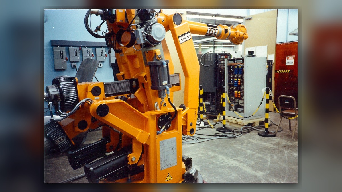
Cover adapted from original image by ArnoldReinhold (CC BY-SA 4.0; source and attribution)
