

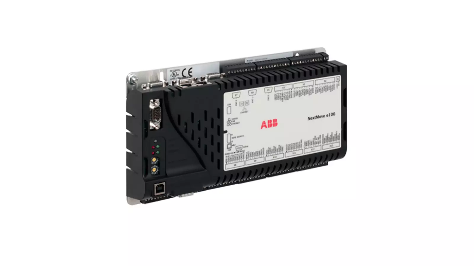
An industrial controller PCB that resets after warm-up needs a record of the failed state. Compare the board input, local rails, reset signal and system event log across the same interruption. A warm component, a dark display or a restart message alone cannot prove which circuit failed.
This printed circuit board repair guide addresses intermittent restarts that appear after a repeatable operating period. It separates supply dips, reset supervision, connections and software-visible events. The methods depend on documented access and the correct test fixture. Do not bypass a watchdog or reset supervisor to keep a machine running.
Printed circuit board repair: the full diagnostic and acceptance guide
1. Build a repeatable timeline
Record the full board and controller identities, firmware version and first error. Note time from startup, operating task, cabinet conditions and connected load. Distinguish a full controller reboot from a display restart or a network link dropping. Save approved parameters and event logs before reset cycles overwrite useful evidence.
Compare a normal run and a failed run using the same job, tool and load where permitted. Preserve recent changes to cooling, wiring, firmware and peripherals. A fault after maintenance may have a connection or configuration cause. Correlation with heat is a useful clue, not proof of a failing capacitor.
2. Separate cabinet conditions from board-local behavior
Check the specified airflow path, fan operation and permitted filter condition. Record ambient and cabinet measurements only at valid locations. Do not treat a hotter surface on an infrared image as an identified defect. Emissivity, reflections, access and the normal power dissipated by the component affect interpretation.
Observe the controller with its intended guards and covers restored for the relevant test. An open cabinet changes cooling and can make the symptom disappear. Local heating or cooling of electronics needs an approved diagnostic method. Uncontrolled heating, liquid spray or condensation can create a new fault and destroy the original evidence.
3. Capture the supply and reset relationship
| Observed sequence | Investigate | Evidence limit |
|---|---|---|
| Input falls before local rails | External source, load and contacts | A board swap does not fix the source |
| Local rail falls with stable input | Converter circuit and connected loads | A meter average may miss the dip |
| Reset asserts with stable measured rail | Supervisor input, manual reset and monitored rails | One monitored point does not cover every supply |
| No electrical event captured | Logging, test bandwidth and other system causes | Failure to capture is not proof of normal operation |
Use only approved test points and a suitable measurement reference. Choose the instrument setup to capture the event and document probe arrangement, bandwidth and load. A handheld meter can show a reasonable average while a brief dip causes a reset. Do not connect a grounded probe to an unknown high-energy or non-isolated reference.
The TI TPS3808 provides a documented example of voltage supervision, reset delay and a manual reset input. Its behavior illustrates why reset timing must be compared with the monitored supply and inputs. It does not identify the supervisor fitted on a particular robot board, and its thresholds are not generic repair limits.
4. Inspect connectors and temperature-sensitive circuits
After isolation and discharge, inspect the affected supply path, connectors and previous rework under magnification. Relate a suspect joint to the circuit and event evidence. A visual crack can support further inspection, but blanket reflow removes the original condition and may damage pads. ESD protection remains necessary during board handling.
If measurements implicate a regulator, capacitor, supervisor or connection, verify the component identity and surrounding circuit before replacing it. Check the upstream supply and downstream demand. Resistance, capacitance or ESR results need a method and valid comparison; a component tester by itself does not recreate the operating transient.
5. Keep hardware evidence separate from software recovery
Use event logs to distinguish supply-related resets, watchdog events and communication recovery where the controller reports them. A watchdog event can have several causes. Do not erase alarms, reinstall firmware or change timing parameters before preserving the existing records. Follow the manufacturer recovery procedure for any required software work.
If the fault follows a particular peripheral or task, examine that dependency alongside the board. A different job that does not restart is not proof of a successful hardware repair. Record which load, interface and software conditions were excluded, and list those that the available test equipment cannot reproduce.
6. Validate beyond a cold power-up
Before power, check the repair locations and required circuit results. Repeat startup and the defined warm-up test using agreed conditions and manufacturer limits. Record run duration, load, ambient conditions and observed rail or reset behavior. The relevant duration should address the original failure window, not an arbitrary universal soak time.
Separate a compatible bench test from installed-system validation. Confirm configuration and the original job under the approved site procedure. If the fault is not reproduced or an input cannot be monitored, retain that limitation in the report. Send the board labels, timeline and measured sequence when requesting a repair assessment.
Reset supervision example: TI TPS3808 product data and data sheet