

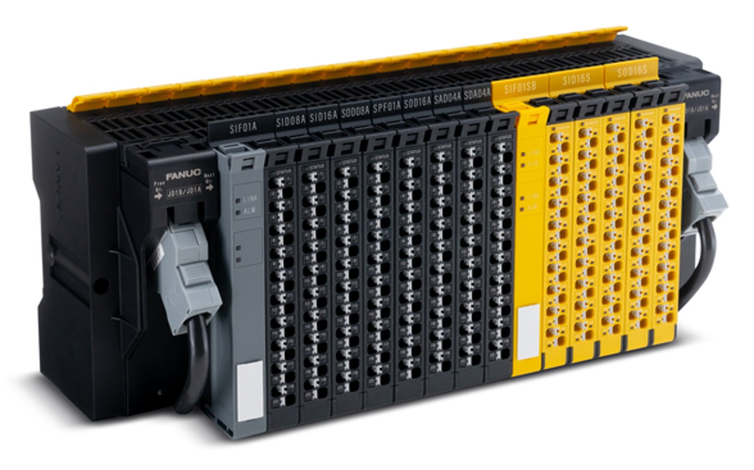
Robot I/O board repair starts by tracing one command or sensor signal through the complete channel. Separate software mapping, field wiring, module power and the board circuit. A controller bit that stays off does not prove a failed input. An output command that turns on does not prove the actuator received power.
This is a fault-specific companion to the printed circuit board repair guide. It addresses ordinary digital I/O, not a procedure for validating safety I/O. Check the exact robot controller, interface, module and terminal documents before testing. Input type, common reference and source/sink arrangements vary between systems.
Printed circuit board repair: the full diagnostic and acceptance guide
1. Identify the exact channel and its expected sequence
Record the module part number, revision, connector, channel and controller address. Photograph the label and terminal map. Preserve the I/O assignment and recent configuration changes. Write the expected sequence: which sensor should change, which bit should follow and when the actuator should respond. Separate an intermittent delay from a channel that never responds.
If several channels fail together, identify what they share. A field supply, common terminal, module connection or network segment can affect a group. Check that shared path before treating each channel as a separate component failure. A module status light does not establish that every field-side supply is present.
2. Trace a digital input from sensor to controller
| Location | Evidence | Question |
|---|---|---|
| Sensor | Supply and actual target state | Is the expected signal generated? |
| Field terminal | Correct signal/reference under the event | Does the signal reach this channel? |
| Module indication | Documented channel and module state | Does the interface recognize the change? |
| Controller address | Mapping and time sequence | Is the correct software bit observed? |
Measure only at documented points using equipment suited to the circuit. Confirm the reference and expected levels from the module data, rather than assuming all industrial inputs are identical. A sensor may appear healthy when disconnected but fail to drive the connected input. Keep the loaded condition and signal timing with the measurement.
The TI ISO1211 is an example of an isolated industrial digital-input receiver. Its data sheet shows why input thresholds, polarity and supporting components matter. This device is a circuit example, not an identified part on a FANUC or ABB board. Use the fitted interface data and installed wiring for actual limits.
3. Trace a digital output from command to actuator
Compare the controller command, output supply, channel terminal and actuator response during the same event. A switched output may use a relay or semiconductor; the test depends on that design. Confirm whether the channel sources or sinks current and which common belongs to the load. Do not assume a channel indicator proves useful load current.
Inspect the external cable, load and specified suppression arrangement before condemning the output stage. A shorted coil, damaged cable or poor return can mimic or cause a board fault. Do not bypass an interlock, force a production output or attach a generic lamp as a test load without an approved machine test plan.
4. Use unpowered inspection to localize board damage
Isolate the equipment, confirm discharge and use ESD controls. Inspect the affected terminal, connector joints and visible channel circuit under magnification. Compare the copper path and surrounding parts with the drawing or a verified identical board. In-circuit resistance and diode checks include parallel paths; they are evidence, not a standalone diagnosis.
A confirmed fault may involve a connector, protection device, receiver, output driver or damaged track. Record the failed function and the measurement supporting each repair. Do not replace all channel parts because one output failed. A proposed substitute needs an exact functional and electrical match, including isolation where applicable.
5. Retest the channel and adjacent functions
Before power, inspect repaired joints, polarity, spacing and the relevant unintended-connection checks. Use the correct fixture to compare expected and observed input states or output responses. Include the channel off-state as well as its on-state. A channel that turns on but cannot turn off has not passed.
Where relevant, test neighboring channels, shared power and communications affected by the work. Record the test load, signal type, timing and limits. A bench fixture may not reproduce the original actuator, noise or cable route. List those gaps before the board returns to the cell.
6. Validate the installed sequence without changing its intent
Restore the approved I/O mapping and check the complete sensor-to-actuator sequence under the site procedure. Confirm normal operation, the expected off-state and the original failure condition. Separate controller communication recovery from channel-level repair. Safety-related functions require their specified validation and documented sign-off, outside this ordinary I/O workflow.
For an assessment, send the module label, exact channel, terminal diagram, expected sequence and observed states. Include the load and supply details, alarms and recent work. These records help separate board repair from a sensor, cable, configuration or actuator problem before a repair scope is agreed.