

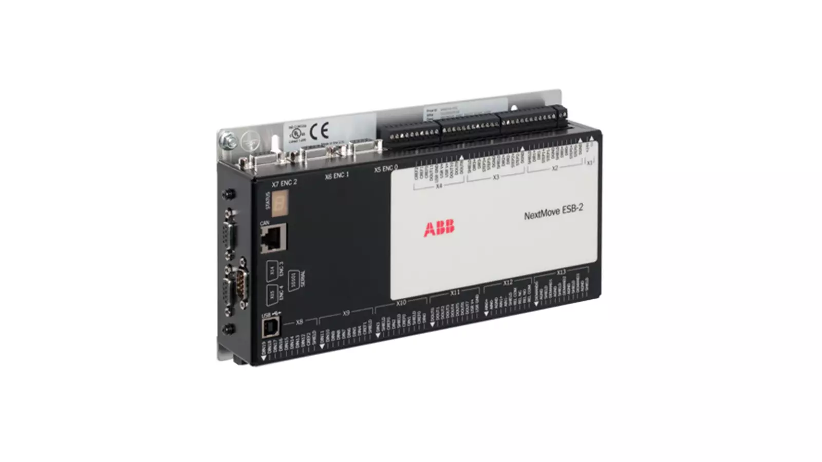
Printed circuit board repair restores a faulty electronic assembly by finding the failed circuit, correcting the cause and testing the repaired function. For industrial robots, this can involve a controller, power board, drive-control board or I/O board. A reset, dark display or missing output alone does not identify the failed part.
This industrial PCB repair guide covers no-power, I/O and warm-up faults. It explains how to separate external wiring from board damage, assess component or track repair, and define acceptance tests. Use the installed assembly documents for pinouts and limits. The process is a diagnostic guide, not a record of a completed customer repair.
Robot circuit board repair: board identity and service assessment
Identify the board before testing it
Record the assembly number, hardware revision and equipment model. Photograph both sides where access permits, including connectors, labels and previous repairs. Keep the full alarm and the conditions in which it appeared. A sales description or a similar-looking board is not enough to establish compatibility.
Preserve firmware, parameters and removable storage through the approved backup process. A replacement may need the correct revision, options and configuration as well as matching connectors. Do not assume that replacing memory or a processor will preserve the machine's setup.
Is the fault on the PCB or outside it?
Before circuit board repair, check the external supply, wiring and connected loads against the equipment documentation. A damaged field cable can pull down an output. A poor connector can cause resets. Replacing a board without correcting that cause may leave the original symptom or damage the replacement.
| Symptom | Board-level possibilities | External causes to separate |
|---|---|---|
| No power or no status lights | Input protection, regulator or shorted rail | Missing supply, fuse, cable or connection fault |
| Repeated resets | Rail instability, reset circuit or connector damage | Supply dips, wiring problems or excessive load |
| One input or output fails | Interface component or damaged track | Sensor, actuator, cable or incorrect signal level |
| Communication is intermittent | Connector, interface or local supply fault | Network cable, termination or configuration |
| Fault appears after warm-up | Temperature-sensitive component or joint | Cabinet cooling, contamination or operating load |
The table gives hypotheses, not a diagnosis. Keep the observed symptom separate from the suspected component. A fuse that opens is evidence of excessive current in its path; it does not identify the part that caused it.
Unpowered inspection: what can you learn first?
Disconnect and isolate the assembly according to the equipment procedure. Confirm stored energy has been discharged using the prescribed method. Use an ESD-controlled work area for sensitive electronics. Never connect a resistance meter to an energized circuit.
Inspect under suitable magnification. Look for cracked joints, damaged connector pins, corrosion, lifted pads and heat damage. A dark area alone does not prove that the nearest component failed. Photograph the finding and trace which circuit it belongs to before disturbing it.
Continuity and resistance checks can help locate an open path or a suspected short. In-circuit readings include parallel paths, so compare them with the schematic, component data or a verified equivalent assembly. A low resistance reading on a processor supply rail may be normal; no single resistance threshold fits every board.
Controlled powered tests: rails, resets and interfaces
Power the board only with a verified pinout, suitable fixture and documented supply conditions. Define current limits and stop conditions from the actual assembly. Do not guess a connector pinout or apply a generic test voltage. Mains-connected and high-energy sections require appropriate equipment and working procedures.
For a suspected supply fault, follow the path from the input stage to the affected rail. Check the regulator output and its enable conditions. If ripple is relevant, record the probe arrangement, bandwidth, load and measurement point. A handheld meter's average reading cannot show every brief voltage dip or switching disturbance.
If rails remain within the specified conditions, examine the next relevant function: reset behavior, interface activity or the affected I/O channel. A signal needs an expected state and timing to be useful. Do not label a processor defective simply because the board does not boot.
Three industrial PCB fault paths to check
No power: follow input protection to the missing rail
Confirm the correct supply at the documented board input under the stated load. If it is present, trace protection, switching and regulation toward the missing rail. Check a fuse and its downstream circuit together. A replacement fuse that opens again suggests the cause remains; do not increase its rating.
If the rail is low, distinguish an overloaded output from a regulator that is not enabled. Any isolation of a load needs a circuit drawing and an approved method. Record the measurement point, expected state and actual result. Low resistance alone does not establish which parallel component has failed.
One I/O channel fails: separate the terminal from the load
For an input fault, compare the sensor state, terminal signal, local supply and controller indication. For an output fault, compare the command, output supply, channel response and external load. Use a suitable fixture where required. Never substitute a load without checking its rating and interface type.
A relay, driver or protection component becomes a repair candidate only when the measurements support it. Recheck the field cable and actuator before returning the board. A short outside the cabinet can damage the replacement output. Safety-related I/O requires its own approved validation, not a general signal test.
Resets after warm-up: capture the failed state
Record time from startup, cabinet conditions and connected load. Where documented test points permit, observe the relevant rail and reset signal across the failure. Separate a board-local change from an input-supply dip or poor connector. Thermal imaging can guide inspection; a warm part is not automatically a failed part.
Do not reflow every joint or replace all capacitors to chase an intermittent reset. Preserve the symptom, identify the affected circuit and record each change. Compare the same load and warm-up conditions after repair. If the failure is not reproduced, state that limit in the report.
Choose the repair from the evidence
Component and connector replacement
Confirm the component identity and failure evidence before replacement. Package shape alone does not establish voltage, current, temperature or functional suitability. A capacitor replacement needs more than matching capacitance; the circuit may also depend on ESR, ripple rating, polarity and physical fit.
Inspect connector joints and the supported copper after removal. Select soldering or rework conditions for the assembly and component. There is no universal hot-air setting for every PCB. Uncontrolled heating can lift pads, damage nearby parts or conceal the original fault.
Pads, tracks and contamination
For a damaged track, establish the intended connection and the reason it failed. The repair must account for current, spacing, insulation and mechanical support. A wire bridge across an unknown damaged area is not a diagnosis. Internal-layer damage may make the repair impractical to verify.
Cleaning also needs a compatible process. Remove residue without damaging coatings, plastics or markings, and verify the board is ready for testing. Restoring a protective coating requires the applicable material and process; simply hiding the repaired area does not prove protection has been restored.
What should a repair acceptance record contain?
| Acceptance stage | Evidence to retain | What it does not establish alone |
|---|---|---|
| Visual and unpowered checks | Repair locations, polarity, joints and relevant short checks | Successful operation under power |
| Controlled bench power-up | Supply, current, fixture, alarms and rail results | Full machine compatibility |
| Interface and functional tests | Stimulus, expected response and observed result | Behavior of untested channels or conditions |
| Defined load and warm-up test | Load, duration, temperatures and current where relevant | Unlimited life or all future operating conditions |
| Machine-level validation | Configuration, interlocks and actual process response | Certification beyond the agreed test scope |
Specify acceptance criteria before testing. Use the manufacturer's limits or the agreed engineering specification. Record the instruments and test conditions alongside the results. “Tested OK” without a stated scope makes it hard to compare bench work with a later site fault.
Repair or replace an industrial board?
Compare fault certainty, damage extent, parts availability, configuration recovery and test access. Severe substrate damage, unavailable programmed parts or an untestable safety function can change the decision. A matching part number does not remove the need to check revision and setup.
There is no reliable flat repair price or turnaround time for every board. Assessment needs clear photographs, the assembly identity and the symptoms. Our robot circuit board repair service is the service entry point. The refinery rush-repair record is a separate event account, not proof that every board can receive the same treatment.
For PCB circuit board repair enquiries, send the board label and fault details to Suntech. Include the machine model, alarm history, previous work and whether a suitable test fixture is available. This helps define a realistic diagnosis and acceptance plan.
Detailed PCB fault guides
Industrial PCB No Power: Supply and Rail Fault Checks
Robot I/O Board Repair: Input and Output Fault Checks
Controller PCB Resets After Warm-Up: Fault Diagnosis
Printed circuit board repair questions
Can a burnt or broken PCB track be repaired?
Sometimes, but first establish the circuit, damage depth and cause. A surface track differs from a plated hole or internal layer. The method must preserve current capacity, spacing and mechanical support. Carbonized substrate, hidden layer damage or an untestable function can make replacement more appropriate.
Does replacing a board require firmware or parameters?
It may. Confirm the assembly revision, programmed devices, licensed options and restore procedure before removal. A repaired board that boots is not proof that the machine configuration is correct. Preserve the approved backup and record any calibration or setup required after installation.
Technical references
These references describe repair methods, standards context and protective materials. They do not certify this website or establish model-specific test limits. Product documents and the agreed repair scope govern the actual work.
Circuit Technology Center: circuit, plated-hole and pad repair