

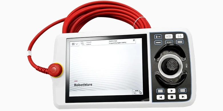
An ABB FlexPendant touchscreen not working is not proof that the LCD needs replacement. First establish whether the picture is normal, whether physical keys respond and whether the controller is still updating the screen. Touch input, image output and system response are separate evidence paths. A frozen application can look like a failed touch panel.
This guide focuses on ABB teach pendant touch faults: dead zones, shifted input and unstable response. It explains what to record, how to separate likely parts and what a repair assessment should prove. It does not assign one screen, cable or procedure to every ABB robot teach pendant. Identify the installed assembly before choosing a test or replacement.
1. Identify the FlexPendant and preserve the original fault
Photograph the terminal label, controller label and cable identifiers. Record the controller software version when it is accessible. Save the full fault text, the affected screen and any recent screen, cable or software changes. An ABB IRC5 FlexPendant description alone is not a complete spare-part specification. Assembly numbers and revisions matter more than a similar front cover.
Observe the fault from the normal operating position before opening the housing. Note whether it starts immediately, appears after warm-up or follows cleaning or impact. Record an existing link to cable position without provoking a live fault. Stop the machine under its maintenance procedure before disconnecting or inspecting the terminal. Keep backup and restoration requirements with the fault record.
2. Separate a dead touch area from a frozen screen
| Observation | Next comparison | What it does not prove |
|---|---|---|
| Live picture, same touch area fails | Repeat the same approved input check at fixed locations | The LCD has failed |
| Input lands beside the target | Check repeatable offset and the specified calibration method | Calibration will repair physical damage |
| Picture and keys stop together | Compare controller state and other available diagnostics | Only the touch layer is defective |
| Random input without contact | Inspect surface condition, mechanical pressure and input assembly | Software is the sole cause |
Use a permitted input-check screen or a non-motion screen. Record locations rather than writing only “touch bad.” A simple grid record can show whether the same edge, corner or strip repeatedly fails. Avoid pressing harder to force a response. Pressure can hide an intermittent contact and add damage to a cracked panel or seal.
3. Check surface conditions before changing calibration
Inspect for a loose overlay, trapped debris, fluid residue and damage at the bezel. Clean only as specified for that terminal, then dry it as required. Confirm that any screen protector and input tool are permitted for the installed unit. Do not generalize glove behavior across generations or assume that a protective film is harmless because the display remains clear.
Calibration is relevant when repeatable coordinate offset is the actual symptom and the equipment procedure provides it. Record the original pattern and the result after calibration. A dead strip, cracked input layer or unstable connector needs a different investigation. Repeated calibration without a stable reference can erase useful evidence while leaving the cause untouched.
4. Distinguish the touch layer, flex connection and display
The touch-sensing layer is often called a digitizer. Its exact construction and replaceable boundaries depend on the assembly. With the unit isolated and opened by qualified personnel, inspect the input flex, connector latch, contact area and routing under magnification. Look for tears, corrosion, damaged locks and a cable trapped by the housing. A visible mark still needs a link to the failed function.
If the correct drawing and test method are available, trace the affected input path and compare permitted signals or substitution results. Keep circuit identity and probe locations in the report. Never borrow pin assignments or supply limits from another pendant. Replacing the LCD just because the word “screen” appears in the complaint confuses image generation with touch sensing.
5. Repair the confirmed cause and inspect assembly pressure
A justified repair may involve an approved input module, damaged flex or connector repair. The assessment should name the confirmed part and supporting evidence. Check the specified part revision, connection orientation and seal arrangement before assembly. Do not assume that matching dimensions establish electrical compatibility, or that a new panel alone restores the original enclosure protection.
After assembly, repeat the input test with the housing in its intended condition. Compare the same grid locations, screen pages and approved operating conditions used before repair. A fault that returns only after the cover is fitted calls for another check of routing, seating and mechanical pressure. Keep this distinction in the record rather than describing a loose-panel test as final acceptance.
6. Define touch acceptance separately from robot safety checks
Record display quality, touch location, edge response, repeated selections, physical-key response and any observed false inputs. State the test equipment and software context. A repair-bench touch test does not confirm emergency-stop, enabling-device or complete cell behavior. Those functions require their own equipment-specific checks before return to service; never bridge a safety circuit to complete a display test.
For an ABB FlexPendant repair enquiry, provide both labels, photos of the failed input pattern and the cable identification. Ask which input checks are included and which require the installed controller. An intact image is useful evidence, but the repair decision should follow the failed input path and verified assembly identity.
General teach pendant troubleshooting and intake checks