

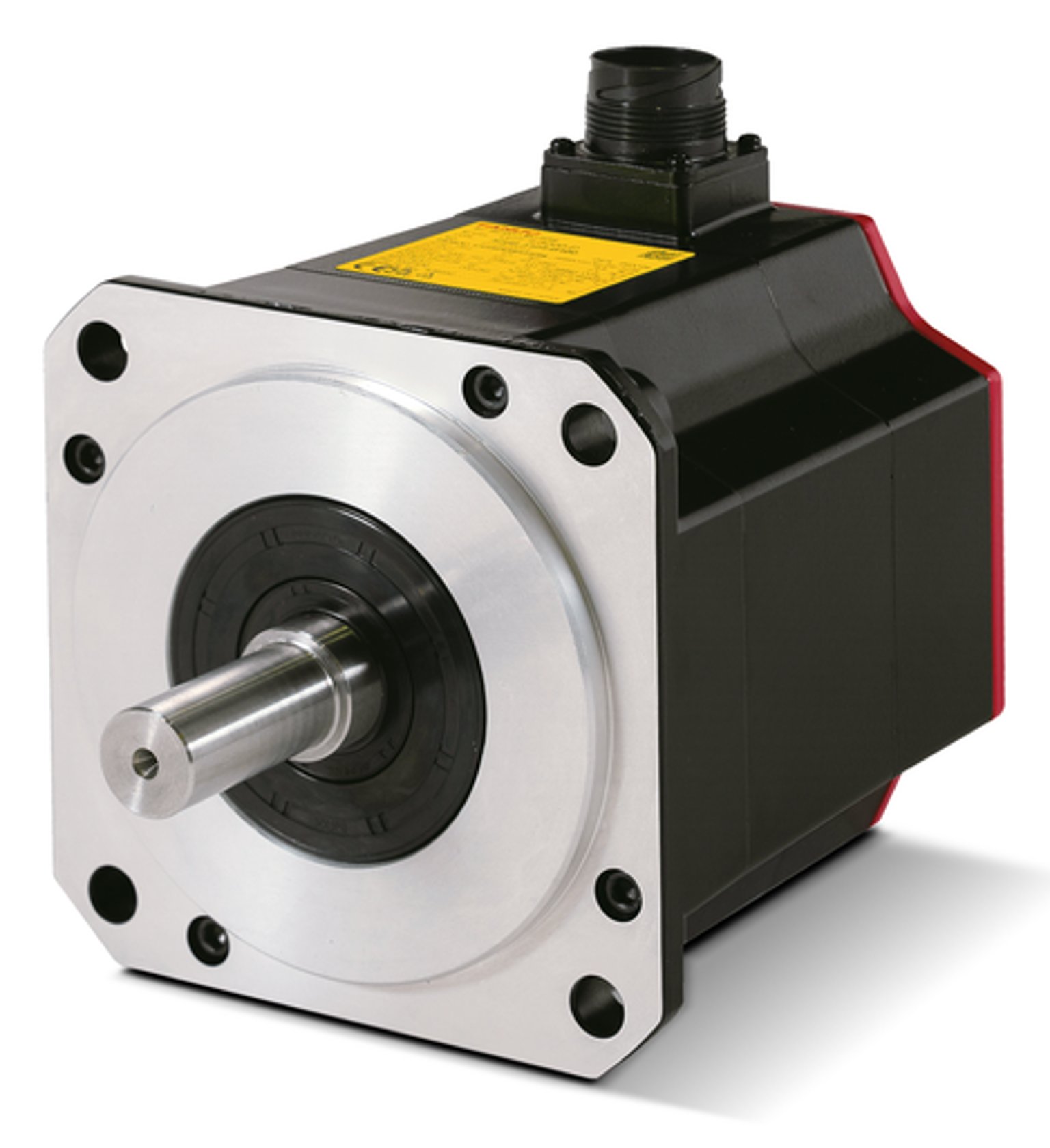
A FANUC robot that reaches the wrong position after a servo motor replacement needs more than an alarm reset. Separate the motor match, the mechanical assembly, the encoder position reference and the selected tool or frame. A motor can turn without proving that the robot knows the correct joint position. Preserve the original data before changing taught points.
This guide covers FANUC servo motor repair and replacement when a position error appears after the work. It is a diagnostic sequence, not a universal mastering command list. The robot model, controller, software, replaced axis and available references decide the correct procedure. A method intended for retained encoder data may not apply after the motor or encoder has changed.
1. Record the changed parts and the position-error pattern
Save the full old and new motor labels, controller identity, affected axis and work sequence. Note whether the encoder, brake, coupling, reducer or cable was disturbed. Keep backups, original mastering records, tool data and user frames with the job. Record which files belong to this robot; a filename alone does not prove that the data is current or usable.
Describe whether the error is fixed, changes with direction or appears only under load. Keep the same tool, frame, payload and reference for a comparison. A shifted fixture or changed tool can move the process point without changing the joint reference. Do not compare unrelated production points and call the difference a measured mastering error.
2. Match the motor, feedback and brake to the installed axis
Check the complete part number, suffix and approved replacement relationship. Compare the feedback device, brake option, shaft, flange and connectors against the fitted robot parts information. A similar power rating or bolt pattern is not enough. FANUC AC servo motor repair also serves machine tools; a CNC product listing does not establish compatibility with a robot joint.
Before powered tests, qualified personnel should check the completed assembly under the required isolation and axis-restraint procedure. Inspect seating, fasteners, coupling engagement, connector locks and cable restraint. Use the specified values and methods for the actual model. Do not guess tightening torque, release a loaded axis or use a brake as the only support for maintenance.
3. Separate joint-reference, tool-frame and mechanical errors
| Observation | Evidence to compare | Avoid this assumption |
|---|---|---|
| Repeatable joint-reference shift | Replacement history and a valid physical reference | Every taught point needs correction |
| Tool-tip shift with joint checks consistent | Selected tool, frame, flange and fixture records | Motor mastering must be wrong |
| Error changes with direction or load | Mounting, coupling, brake and mechanical findings | A software offset can fix wear |
| Feedback alarm or unstable position display | Exact message, cable and feedback identity | Repeated mastering will repair communication |
Treat the pattern as a branch to investigate, not a final diagnosis. More than one change may be involved. If a new motor, a different tool and edited frames were introduced together, restore a controlled comparison using the approved records. Check one documented variable at a time. A single successful move does not isolate the cause.
4. Choose FANUC robot mastering for the actual maintenance event
Mastering establishes the relationship between encoder information and a known mechanical joint reference. Before selecting a method, establish what reference remains valid and what changed during the work. A controller backup, a mark on the housing and a saved encoder count are different forms of evidence. None should be treated as interchangeable without the matching robot procedure.
If a method relies on an earlier reference and unchanged feedback conditions, a motor or encoder change may invalidate those conditions. Confirm the permitted method with the maintenance documentation for the exact robot and controller. Do not copy another robot’s counts, select a convenient reference or force a valid-status flag. Missing reference evidence needs a proper recovery plan before motion.
5. Investigate feedback faults and brake behavior separately
If feedback alarms remain, keep the full message and event order. Inspect the specified cable path, connectors and device identity before treating the issue as calibration. An intermittent feedback connection can invalidate a position comparison. Electrical tests need the proper drawing and isolated test boundaries; do not apply an insulation tester to connected feedback electronics.
For suspected FANUC servo motor brake repair, distinguish a release-command problem from a brake that drags or does not hold as specified. Record the approved test conditions and the measured evidence. Brake release, motor rotation and stable joint position are separate results. Do not defeat the brake circuit or change position offsets to hide a mechanical or holding fault.
6. Verify position before releasing the production job
After the approved assembly and reference procedure, check the affected axes against the specified references. Then verify the selected tool and frame, clearance and relevant path under the permitted safeguarded sequence. An alarm-free controller is not a measurement of geometric accuracy. Keep the original fault trigger and the acceptance method clear before any production run.
The test record should name the robot, replaced part, reference method, tool, frame, load and actual observations. State the instrument, measurement locations and acceptance limits where measurements were made. Separate bench results from installed-cell verification and list untested conditions. Do not invent a standard run time, position tolerance or successful repair result.
What should you send for a FANUC servo motor repair assessment?
Send both motor labels, robot and controller details, the affected axis, the full alarm and the work sequence. Include the available backup and reference status, plus a clear description of the position difference. Say whether the motor, encoder, brake or mounting was changed. This helps distinguish part matching, feedback repair, assembly work and installed position recovery.
FANUC spare parts: full part number and compatibility evidence
FANUC servo drive repair: alarm and connected-circuit checks
Servo motor encoder and feedback fault checks
Servo motor brake not releasing: diagnosis and repair checks
Servo motor repair assessment and enquiry
Manufacturer reference: FANUC robot service and equipment identification