

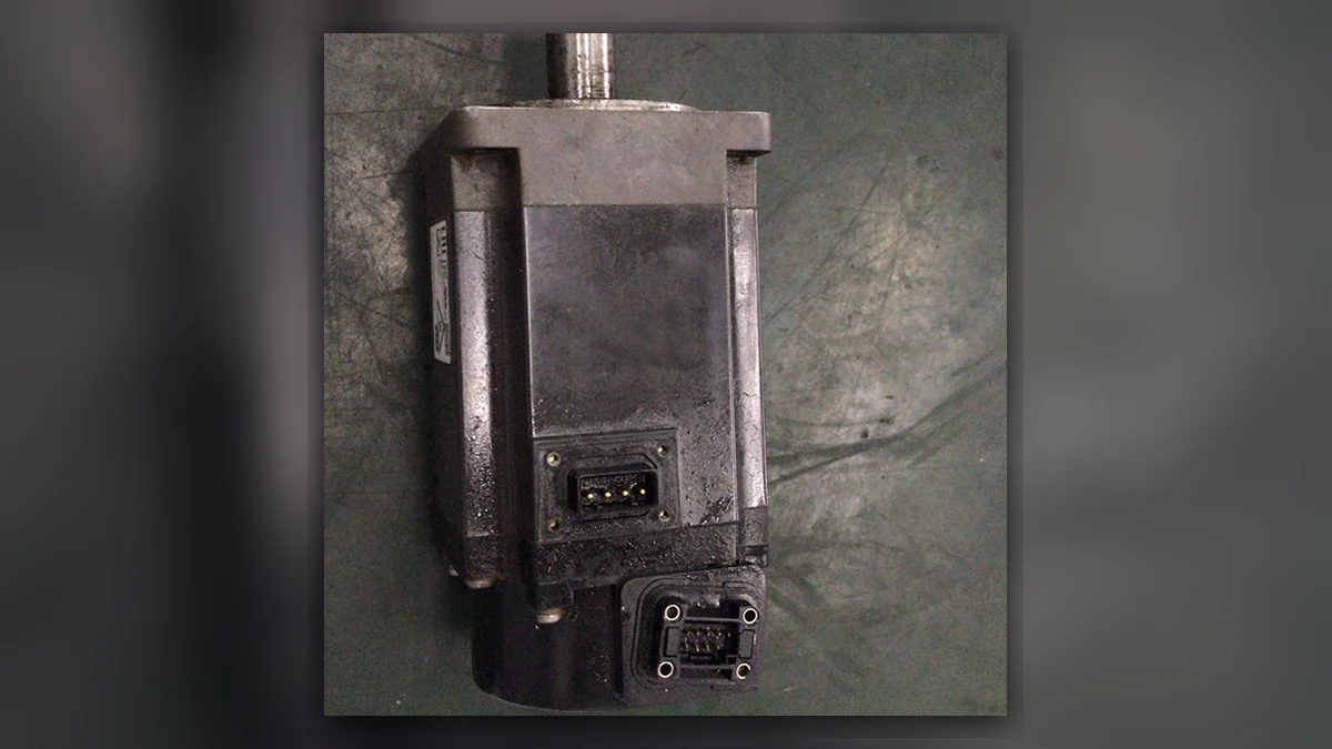
A servo motor works as part of a motion system with feedback. The system compares the motion command with the measured result. It then adjusts the drive output. This helps an axis control its position, speed or torque. The limits depend on the whole machine.
This guide covers industrial servo motors in robots and factory systems. It explains four parts: the motor, drive, feedback and load. Each has a different role. Small hobby servos can use different signals and test methods. Their guides may not apply to a factory robot.
What do position feedback and the error signal mean?
In a position control system, the commanded position is the requested axis location. Position feedback is the measured location. The difference is the position error signal, expressed in the same units and reference frame. The controller uses that error with other control terms to adjust motion. The sign, scale and limits depend on the machine. A large error can come from a jammed load, not only a failed motor.
Open loop control does not use measured output to correct that output in the same way. Closed loop control systems do use feedback. Yet feedback systems have limits. Delay, sensor noise and a loose coupling can reduce precision control. Test the result at the load as well as the motor shaft.
Absolute encoders can report a coded shaft position. That does not mean robot mastering survives every encoder or motor replacement. Check how the machine stores its reference. Dynamic response describes how the axis follows a changing command. Judge it with a defined move and load. A short peak-torque test cannot prove the rating for continuous operation. Review heat and duty across the overall system.
What is inside a servo system?
To define servo system requirements, start with the job. What must move? State the travel or angle, speed, load and duty cycle. Then check how the system measures motion. Power alone is not enough to choose a motor. Load inertia, feedback type and heat also matter.
| Part | Function | Identity or condition to check |
|---|---|---|
| Motion controller | Produces the requested movement | Axis configuration, program and reference |
| Servo drive | Controls electrical output to the motor | Drive model, supply and compatible feedback |
| Motor | Converts electrical input into mechanical output | Complete model, winding and mechanical condition |
| Encoder or resolver | Provides feedback used by the system | Type, interface, connection and reference data |
| Coupling and transmission | Connect the shaft to the machine load | Alignment, backlash and actual load |
| Brake, where fitted | Holds or stops under its specified function | Rating, control and the machine procedure |
The motor label does not describe the whole system. Some units have built-in electronics. Others need a separate drive. Check the wiring and manual first. A test for one design may not suit another.
How do feedback and servo drives control motion?
The controller sends a motion command. The drive adjusts the motor output. Feedback reports the measured motion. A position axis often has several control loops, one inside another. Their design and location vary. Check the loops used by the actual motor and machine.
Feedback does not fix loose parts. An encoder can report motor shaft motion even when a loose coupling slips. Backlash can also affect the load. Compare the workpiece result with the axis data. Do this before blaming the encoder.
AC servo motors, DC servos and hobby servos
Many industrial AC servo systems use a brushless motor with permanent magnets. The motor needs a matched drive and feedback device. Other systems use other motor designs. The word servo describes a control role. It does not define the winding, voltage or plug.
A hobby servo often contains a motor, gears and control board in one small unit. It may accept a simple command signal. That design does not define how to test a robot axis. For an industrial replacement, check the full model. The drive, feedback, brake and shaft must all match.
Which operating conditions matter when choosing a motor?
Check speed and torque across the full cycle. A peak rating is not a continuous rating. A short burst to speed up a load differs from holding that load all day. Also check room temperature, cooling and mounting. These can affect the usable rating.
Load inertia affects how the axis speeds up and responds to commands. Include the tool, payload, gears and other driven parts. Use the maker's sizing method. Save the assumed cycle with the result. No single inertia ratio proves that every axis will work.
How can you separate motor, cable, drive and load faults?
Record when the fault starts and save the full alarm. Is it at power-up or servo enable? Does it follow a certain pose or warm-up period? Find the first event. Later alarms may be effects of the same fault. Use this record to choose the next check.
| Symptom | Useful distinction | Evidence to retain |
|---|---|---|
| Axis will not enable | Missing permission, feedback issue or drive fault | Controller and drive status, full alarm and mode |
| Overcurrent during movement | Electrical fault or excessive mechanical load | Axis, movement, tool load and preceding events |
| Noise or vibration | Bearing, coupling, load or control issue | Speed range, direction, location and repeat pattern |
| Position error changes with pose | Cable flex, loading or reference problem | Pose, feedback alarm and recent cable work |
| Motor becomes unusually hot | Duty, cooling, load or electrical condition | Operating time, ambient conditions and measured values |
The table is a way to organize evidence. An alarm does not prove that a motor, encoder or drive has failed. Do not tune parameters simply to hide an unexplained mechanical or electrical problem.
What do winding and feedback checks establish?
Before unpowered checks, isolate the machine. Follow its discharge and access procedure. Use the specified method to measure the motor windings. Note the temperature and meter resolution. These matter when resistance is low. Keep the method with the readings so they can be compared.
For an insulation test, use the specified voltage and connections. Disconnect the devices listed in the procedure. An unsuitable test voltage can damage the drive or feedback circuit. Encoder and resolver checks also need the correct interface details. Do not guess the supply or pinout.
Check bearings and the shaft against the specified limits. Record the load used for the check. The brake may need a separate test. Many motor brakes hold a stopped axis. They are not general emergency stop devices. Use the specified release and test method.
Repair or replace: what must match?
Keep the full motor part number, including each suffix. Check the shaft, flange, feedback, brake, plug and electrical rating. Use the machine documents for this check. A motor that fits may still be the wrong type. Agree the condition and test scope for a used part.
A replacement can affect feedback references, commutation data or robot mastering. Keep the approved backups. Follow the maker's procedure for the exact machine. Moving an encoder can change the position reference. An identical-looking motor does not prove that the reference stayed correct.
How should a repaired servo motor be tested?
Agree what the repair shop can test. Some checks need the actual machine. Record the motor, drive, fixture and speed range. Keep alarms and measured results with the report. A no-load run does not prove how the axis will behave in the full site cycle.
Set load, warm-up, brake and feedback checks from the product limits. Record each test duration and condition. After fitting the motor, check the axis reference and response. Follow the machine procedure. A bench test is one part of acceptance. It does not cover every robot task.
For a specific example, see Epson SCARA motor fault assessment. For drive-related symptoms, compare FANUC servo drive fault checks. These pages address different parts of the system.
Prepare a motor repair enquiry
Send the motor and drive labels, machine model, full alarms and conditions that reproduce the fault. Include cable or mechanical work performed before the problem started. Use the servo motor repair service page to review the assessment scope, or contact Suntech with the records.
FANUC's ALPHA i-B and BETA i-B servo overview provides a manufacturer example of industrial servo products. It is not a compatibility statement for every robot or motor. The checks in this guide are technical guidance, not results from a completed customer repair.
For a heat-related fault, compare the load, brake and feedback checks in our servo motor repair overheating guide.