

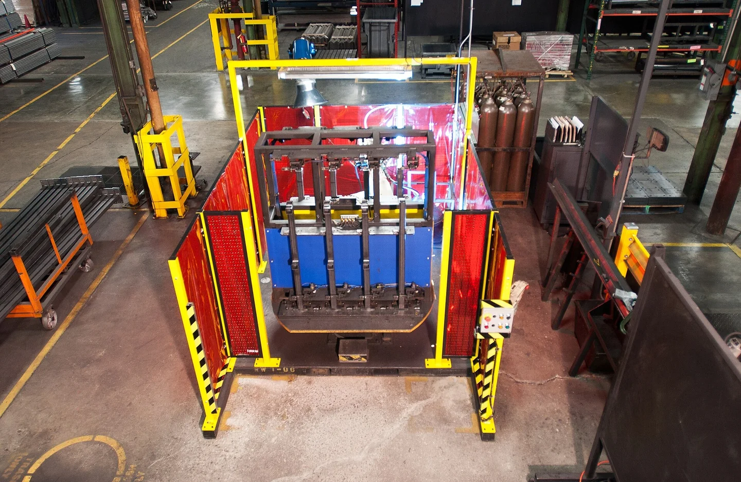
Robotic welding uses a programmed robot to move a welding tool and control the process. A welding robot needs more than an arm. The cell also needs a power source, fixtures, process controls and guards. The part fit, tool condition and weld procedure all affect the result.
This guide explains how welding robots work and where they fit in production. It shows how to tell a weld fault from a motion fault. It also lists records for a repair review. Match the settings and test limits to the material, joint, process and actual machine.
What other welding applications and processes need different checks?
Common types of robotic welding include arc and resistance processes. Within arc welding, TIG welding uses a non-consumable tungsten electrode. The name tungsten inert gas describes its shielding approach. A TIG system may need separate filler feed. Check electrode condition, gas coverage and the specified start sequence. A wire-feed fault branch from a MIG cell does not cover every TIG fault.
Laser welding uses a focused beam as the heat source. Its optics, joint fit, beam path and protective enclosure need process-specific checks. Plasma welding uses a constricted arc and has different torch and gas requirements. Robotic welding systems must coordinate the actual source and tool. Neither process is a drop-in change of software for a standard arc cell.
What are the advantages of robotic welding over manual welding?
Automated welding can repeat a defined path and timing on a stable joint. Those are useful advantages of robotic welding, but they do not remove process variation. A human welder can adjust to a changing part during manual welding. A robot needs a defined way to detect or control that change. Machine vision or seam sensing may help, with the correct setup and validation.
An industrial robot in the automotive industry may weld a repeated part in a fixed cell. A collaborative robot may serve a different loading pattern. Both need an application risk assessment, including the torch and hot work. Compare access, part mix, inspection and recovery work. Choose the complete process rather than assuming that any robot guarantees a sound weld.
How does a robotic welding cell work?
First, the cell confirms that the part is present and clamped. The robot moves toward the joint. The welding unit reports that it is ready. The program then starts the process. The robot and welding unit follow the set sequence. After the weld, the cell confirms completion. It releases the part when the process permits it.
A start command does not prove that a weld was made. The unit may be waiting for wire feed or a ready signal. Save the robot step and the welding unit state. Compare their times to find which event came first.
| System | Role in the cell | Evidence worth recording |
|---|---|---|
| Robot and controller | Position the tool and run the motion program | Program, step, axis, pose and alarm text |
| Welding power source | Supply and control the welding process | Process selection, readiness and fault history |
| Wire feeder and torch | Deliver wire and guide the arc process where fitted | Wire path, consumables and observed feed response |
| Fixture and positioner | Locate and support the workpiece | Clamp state, part fit-up and positioner reference |
| Cell controls | Coordinate permits, starts and completion | Signal names, sequence and timeout |
| Safeguards and extraction | Control exposure and access for the installed task | Device state and the applicable inspection record |
Arc welding and spot welding need different checks
Arc welding robots
In wire-fed arc welding, the cell must link motion, wire feed, gas and power. Torch angle, gap and travel path all affect the joint. Use the defined weld procedure for that part. A setting from another material or joint may give a poor result.
MIG and MAG are related gas metal arc welding processes. Their shielding gas and uses differ. Other robotic arc work may use a different process or tool. Check the actual setup. Do not treat every welding robot as a wire-fed system.
Spot welding robots
Resistance spot welding applies force and current through electrodes at a joint. Check the electrodes, force, cooling and weld schedule. A spot welding gun needs a different fault record from an arc torch. The arms may look similar. Their process checks are not the same.
When are robots that weld useful?
Repeat joints with stable parts are a useful starting point. The tool needs access to each joint. The cell also needs sound clamps and a way to inspect the weld. Small batches can suit automation too. Include program changes, fixtures and loading time in the review.
Start with a sample part that matches the job. Record joint access, gap variation, material and test needs. Check reach, tool mass and the full motion area. Payload alone does not prove that a setup will work. Tool inertia, hoses, positioners and process limits also matter.
Why can a robot follow the path but produce a bad weld?
Motion and weld quality affect each other, but they are not the same check. The arm may repeat its path while the weld changes. A dirty contact tip, poor wire feed or bad part fit can cause this. A moved fixture can also shift the joint away from the taught path.
Check the part and process against the approved baseline first. Do this before teaching new points. If the torch or mount changed, check the tool center point by the specified method. Record the old and new values. A path change that hides a loose fixture can cause a fault on the next batch.
| Symptom | First comparison | Record before replacement |
|---|---|---|
| No arc after a start request | Robot command versus source readiness and feedback | Program step, signals and power-source alarm |
| Wire feed is irregular | Feed path, consumables and actual feeder response | Wire type, spool condition and the affected stage |
| Weld location has shifted | Fixture, tool mount, TCP and work frame | Recent changes and measured joint position |
| Welding stops during a pass | Process fault versus robot or external stop | First alarm, timestamps and visible defect |
| Quality changes after warm-up | Process conditions, cooling and wear | Duration, production load and inspection result |
These checks guide the diagnosis. They do not prove which part has failed. Follow the installed system's access and isolation procedures. Do not bypass its guards or protective functions to repeat a cycle.
What should maintenance cover?
Use the robot, torch, source and positioner manuals to plan maintenance. Check cables and hoses through the working poses. Look for rubbing, tight spots and repeat bends. Check consumables and cooling as the process requires. A clean torch does not prove correct gas flow or electrical contact.
Keep planned tasks apart from fault repair. Record the model, service point, condition found and work done. Photos should show the inspected part and machine. A stock photo can explain a topic. It does not prove that a task was completed.
Which existing model guide should you use?
For an arc-start or wire-feed symptom, use the FANUC ARC Mate 100iD fault guide. For a tool reference change after hose work, see ARC Mate 120iD hosepack and TCP checks.
The OTC FD-V8 interruption guide follows stop and return signals. The YASKAWA AR1440 torch guide covers wire stick-out and collision evidence. Match the complete model and installed process before applying a procedure.
How should repair results be accepted?
Agree the test scope before repair. A controller or drive bench test differs from a weld on the site fixture. Define the motion test, tool checks, process trial and weld inspection. Use the specified quality standard. A weld that looks good may still need other tests.
- Identify the robot, controller, welding source, torch and positioner.
- Preserve programs and settings through the approved backup process.
- Record the repair, test conditions, alarms and any remaining limits.
- Validate motion, process signals and the actual joint inspection within the agreed scope.
Visit the welding robot repair category for model guides, or send Suntech the equipment identity and fault record. These details help define whether the next step concerns the arm, process equipment, tool or cell controls.
Manufacturer reference
FANUC's ARC Mate series overview confirms the arc-welding application context. It does not establish that every listed model, process option or repair is available for a particular installation. The diagnostic and acceptance tables above are general engineering guidance, not a reported customer repair.