

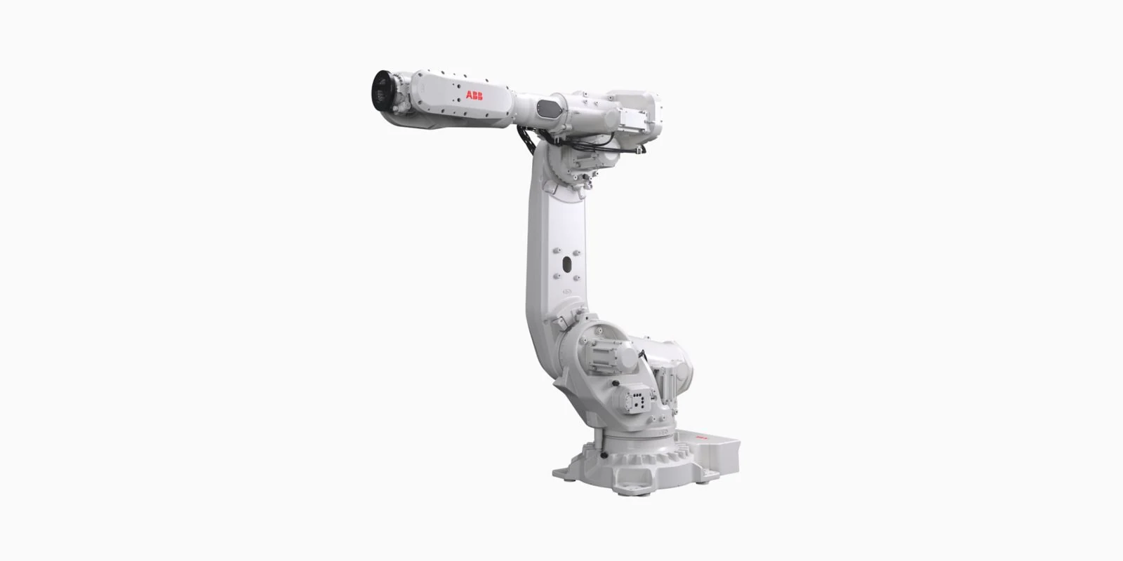
Choosing an arm for robot replacement starts with identifying the installed system. The replacement must suit the controller, drive hardware, mechanical installation and task. A matching brand, similar reach or familiar connector does not establish that two arm assemblies are interchangeable.
This checklist focuses on industrial equipment assessment. Keep the original fault record before selecting an assembly: a stopped cell may need a tool, cable or control-system repair rather than a whole arm. The decision should follow the evidence and the recovery requirements.
An industrial robotic arm should be assessed as part of its complete robot controller and cell configuration. Record the robot arm identity and the control system together before parts are selected.
Define what is being replaced
The word arm can refer to a complete manipulator, a link, a wrist assembly or an educational kit. State the boundary clearly. An assembly supplied without cables, motors, calibration records or its original controller may involve a different recovery scope from a complete robot system.
Record whether the equipment is intended for production, teaching or a research task. These use cases can have different duty, load and integration requirements. A demonstration of movement does not establish suitability for the original factory task.
Identity records come before a compatibility claim
| Record | Installed equipment | Proposed replacement |
|---|---|---|
| Arm identity | Full model, serial number, options and revision. | Full identity and documented configuration. |
| Controller and software | Controller model, system software and installed options. | Evidence that the actual controller supports it. |
| Drive and feedback hardware | Motor, drive, feedback and cable labels. | Documented electrical and feedback compatibility. |
| Mechanical installation | Mounting orientation, base details and tool interface. | Confirmed mounting and task clearances. |
| Recovery records | Programs, parameters, calibration and frame backups. | Required data and manufacturer recovery procedure. |
Photograph full labels rather than transcribing only a shortened model name. Keep suffixes and revisions legible. If any item is unknown, list it as an open question for the supplier or service engineer. Similar appearance cannot fill a missing compatibility record.
Check load and workspace across the complete task
The tool, gripper, workpiece and attached equipment all contribute to the load. Check mass, centre of gravity and inertia against the applicable model limits. A single payload figure does not describe every permitted combination. Keep the load model used during assessment with the equipment record.
Reach must be checked with tool orientation and clearance. Review approach, operation and retreat, including nearby fixtures and cable movement. A larger arm may create new space constraints; an arm with similar reach may still have different joint limits or wrist movement.
Manufacturer model-family references: FANUC robots by series and the actual model documentation.
For another example of model filters, see KUKA industrial robots. Compare complete configurations rather than transferring specifications between brands.
Controller, drives and cables form one compatibility problem
The controller must support the arm and its configuration. Review power, feedback, drive hardware, harnesses and software together. A plug that fits is not evidence that voltage, pin assignment, feedback or control parameters match.
Also identify external axes, process interfaces and the cell PLC sequence. A robot that jogs independently can still be missing the signals or functions used in automatic production. Keep protective functions and their validation within the system review.
Backups and calibration determine the recovery work
Preserve programs and system records before dismantling or configuration changes. Establish which records belong to the controller, arm and tool. A backup from one assembly should not be assumed to supply correct calibration data for another serial number.
The recovery method depends on the system. Ask whether the work requires mastering, calibration, frame checks, tool data changes or application setup. Record the manufacturer procedure and the person responsible for each step. Do not assume that restoring a file completes the recovery.
A tool centre point defines a working reference relative to the tool flange. A replacement or remounted tool may need its reference checked even if the arm model is unchanged. Workpiece frames and fixtures also need review when their physical positions change.
A manufacturer explanation of tool reference data is available in Universal Robots TCP configuration. The procedure for your installed controller may differ.
Assess the condition of a used or repaired arm
Request available service history, collision records, storage conditions and details of previous work. Ask how the unit was tested and which equipment was used. Separate an observed result from a general statement such as tested or working.
A useful test record identifies the arm and controller, software, tool, load, path, run time and alarms. Results should relate to the intended application. A video without these conditions may show motion but cannot establish repeatability, compatibility or performance in your cell.
Agree on acceptance before returning to production
- Confirm identity, mounting and all required connections against the approved configuration.
- Verify recovery data and protective functions using the applicable procedure.
- Check relevant motion, reference points and the planned workspace under controlled conditions.
- Run representative paths with agreed loads and process conditions.
- Record alarms, measured results, remaining restrictions and the handover decision.
Define the acceptance limits and measurement method before testing. Reuse the conditions that exposed the original problem where appropriate. A brief unloaded run is not equivalent to verification of the production cycle.
Repair the existing unit or replace the assembly?
Compare the diagnosed fault, repair scope, parts availability and recovery work with the evidence available for the replacement. Consider installation and validation as part of the work, not just the assembly itself. Obtain a case-specific assessment rather than assuming replacement is always faster.
Can one arm for robot projects cover every application?
No single arm suits every task. A research project, palletizing cell and painting process can need different motion, environment and integration features. State the original task and required conditions before comparing equipment.
For motion and reference concepts, read robot robotic arm motion checks.
For fault isolation before an assembly decision, use the industrial robotic arm repair guide.
Submit labels, fault records and replacement details through the contact page to clarify the assessment and quotation requirements.