

FANUC servo drive repair begins with the exact alarm, the installed controller and the drive module label. A drive alarm can involve incoming power, the motor circuit, feedback, communication or load. It is a reason to investigate the system, not proof that the amplifier alone has failed.
This article focuses on fault records and part identification for FANUC robots. The phrase FANUC servo amplifier repair also appears in CNC service information. Robot controllers and CNC systems can use different hardware and procedures. Identify the application first, then use the documentation for the actual system.
Identify the controller before the drive module
Record the robot model, controller family, cabinet type and software version. Photograph the complete drive label and each connected cable label. Keep the full part number and revision, rather than only a short model name. Note the affected axis and whether the module serves one or several axes.
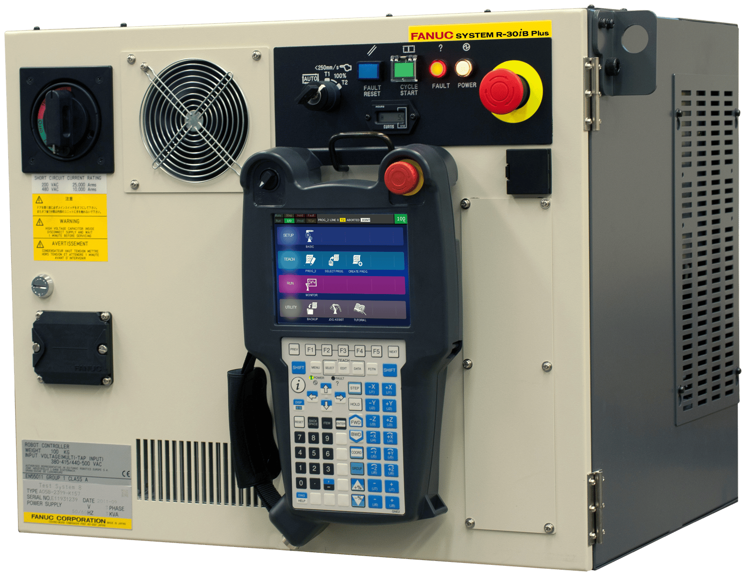
The R-30iB Plus is a robot controller family. A cabinet image helps identify the system context, but does not identify the amplifier fitted inside it. Cabinet options and installed equipment need their own records. An advertised replacement should be checked against those records before it is considered.
Manufacturer reference: FANUC R-30iB Plus controller.
What does the drive alarm tell you?
| Observed fault | Record first | Systems to distinguish |
|---|---|---|
| Alarm at power-up | Full message, axis, timing and whether several modules report faults. | Supply conditions, controller state, communication and module faults. |
| Alarm when servo power is enabled | First alarm and the change in ready or enable status. | Power circuits, motor connections, feedback and drive status. |
| Alarm on acceleration or under load | Direction, speed, tool, load and recent mechanical work. | Load, mechanical resistance, motor circuit and drive operation. |
| Feedback or communication fault | Exact message, affected devices and recent cable work. | Feedback cable, connector, matching device and communication path. |
| Fault after a period of running | Run time, ambient conditions and cooling observations. | Cooling, load, connections and parts that change with temperature. |
These are assessment categories, not a universal alarm-code chart. A code must be read in the manual for the installed controller and software. Keep the complete message and any axis detail; the same informal description can refer to different faults.
Separate the drive from connected circuits
Start with the evidence that is available without changing parts. Review the last normal cycle, the first fault and any work performed between them. Keep program and parameter backups before changes. Follow the equipment procedure for isolation and stored energy before electrical inspection.
Power, motor and mechanical load
An overcurrent or overload message can involve the motor circuit or the load being moved. Record whether the event occurs at rest, during acceleration or only with a particular tool. A test performed without the production load may not reproduce the original condition.
Check results should name the circuit and test method. Motor insulation, winding and brake checks require methods suited to the motor and its connected electronics. Do not apply one generic electrical test to every connector. Where the findings point to the motor, keep that work separate from the drive repair scope.
Feedback, cables and communication
Compare the fault with cable movement, recent connector work and any change of motor or feedback device. Record visible damage and label information. A loose connection can create an intermittent fault, but appearance alone does not prove the complete circuit is sound.
The technician should state which connection was tested and under what conditions. Unplanned swapping of drives or feedback connections can change configuration and make the original evidence harder to interpret. Use only a documented comparison method for the installed equipment.
When should a drive be repaired or replaced?
A component decision follows the inspection findings. Record the damaged or suspect section, the tests performed and the effect on the connected system. A repair report should distinguish confirmed findings from parts replaced as a precaution. Replacing a board without resolving an external fault can leave the same alarm in place.
Repair and replacement also require an agreed verification plan. Include the time needed for setup, software or parameter work and installed tests. Compare options using the same scope. A module price and a complete repair-and-test service are different items.
Match the full part number and configuration
- Compare the complete part number, suffix, revision and supported controller application.
- Identify the motor, feedback system, cable connections and any shared module functions.
- Check the required firmware, settings and backup procedure in the applicable documents.
- Confirm the checks required after installation, including configuration or calibration where specified.
Matching plugs, case size or a similar label prefix is not enough to establish compatibility. FANUC parts records should include all identifying details. A CNC servo amplifier and a robot drive should not be treated as interchangeable because both carry the same manufacturer name.
For board-level rail, I/O and reset checks, use the printed circuit board repair guide.
What should the test report include?
A useful FANUC servo drive repair report lists the incoming symptom, confirmed findings, work done and tests completed. It identifies the module tested and states the test arrangement. A bench result shows performance under that arrangement, rather than every condition in the original robot cell.
Installed checks should follow the approved procedure and the agreed acceptance criteria. Review communication, feedback, servo enable and controlled axis motion as relevant. Then test the original fault trigger with a defined load, speed and run duration. Keep any repeat alarm with its time and operating state.
For a robot that powers up but will not run, use the FANUC robot troubleshooting guide to separate start conditions from drive faults.
For the wider system, read industrial robotic arm repair.
Prepare a clear repair enquiry
Send the robot and controller models, drive label photos, complete alarm text and the event timeline. Include the affected axis, load, recent changes and tests already completed. State whether you need fault assessment, a repair scope or confirmation of a proposed replacement. The same evidence supports each decision.
Related service information: robot servo drive repair.
Submit the fault and part details through the contact page.
Manufacturer service reference: FANUC robot service.
For planned service and inspection records, use the FANUC robot maintenance checklist.