

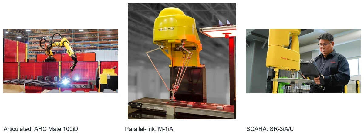
Industrial robotic arm repair starts by separating the symptom from the failed part. A stopped arm may have an unmet start condition, a drive alarm, a cable fault or a mechanical load problem. Record when the fault occurs and which axes are affected before choosing a test or replacement.
This guide explains how robot arm components work together and what evidence helps distinguish their faults. It covers industrial equipment used for handling, welding, painting and assembly. A desktop teaching arm can use a different control system, so its repair method does not establish a procedure for a factory robot. Industrial robot repair also needs the cell controls, tooling and operating history.
Before tracing a fault, review robotic arm components and types to distinguish the arm, tool and cell controls.
Which robotic arm components can cause the fault?
The arm, robot controller, drives, motors and cables form one motion system. A fault in one part may produce an alarm in another. Use the full system identity and event sequence to narrow the scope.
| Part or system | Useful observation | What the observation does not prove |
|---|---|---|
| Robot controller and cell controls | Mode, program selection, active alarms and external-ready signals. | A powered display does not prove that motion is enabled. |
| Servo drive | Exact alarm, affected axis and the stage at which it returns. | Overcurrent alone does not identify a failed drive. |
| Servo motor and feedback | Noise, heat, brake state and position-feedback alarms. | A stationary axis does not prove a burned winding. |
| Cables and connectors | Visible damage, part labels and faults linked to arm position. | A symptom that changes with position does not identify one cable by itself. |
| Mechanical load and tooling | Recent tool changes, contact, binding or unusual play. | A position error does not establish a worn gearbox. |
Start with the fault pattern
All axes stop or automatic motion will not start
First compare the controller state with the cell controls. Note the selected mode, active program, hold state and device-ready signals. If manual motion works but automatic motion does not, preserve the start sequence and PLC signals. This pattern calls for a review of control conditions before an axis part is blamed.
One axis stops, shakes or loses position
Record the axis, direction, speed and load. Note whether the symptom appears at startup, on acceleration, at one pose or after the cell warms up. Keep the first alarm as well as later messages. A drive, motor, feedback connection or mechanical load can cause similar motion symptoms.
Separate electrical, cable and mechanical evidence
Robot troubleshooting works best when each test answers one question. An inspection may identify a loose connector or damaged cable jacket. Electrical checks can then assess the circuit named in the alarm. Mechanical checks review the load and motion path. Keep these findings separate in the repair record.
- Compare the last normal cycle with the first faulty cycle. Record tool work, software changes, collisions and recent replacements.
- Retain the exact drive and motor labels. Identify feedback, brake and power connections from the correct drawings.
- Use the equipment procedure for isolation and stored-energy checks before cabinet or axis work.
- Record measured results, test conditions and the instrument used. A pass/fail note without conditions is hard to review.
Avoid repeated resets as a substitute for diagnosis. They can hide the order of events and change the fault pattern. Fault finding should preserve protective functions and use the approved test state for the cell.
Industrial robot repair: which test separates the fault?
Industrial robot repairs need a testable plan. Start with the same tool, load, path and failure stage. Compare the first fault with the last normal cycle. Similar alarms can have different causes, so use the branch below to choose evidence, not a part to replace.
| Fault pattern | Comparison that helps | Evidence needed before a repair decision |
|---|---|---|
| Axis stops as motion is enabled | Compare the first alarm, brake command and feedback state at the same event. | A brake command is not proof of brake release. Record the applicable circuit test and load support method. |
| Fault appears at one pose | Compare the same joint position with cable routing and connector condition. | Inspect the full cable route while isolated. Use pin-to-pin tests from the correct drawing; do not flex a cable beside a moving arm. |
| Position shifts after a tool change | Compare the tool mass, center of gravity, TCP and fixture reference with the approved setup. | A changed tool or frame can move the result without a failed motor. Separate reference errors from joint-motion errors. |
| Alarm appears only after warm-up | Compare the same cycle from cold start to the fault, including current and temperature records. | Note elapsed time, ambient conditions and cooling state. Heat at one point alone does not identify a failed component. |
For electrical tests, isolate the named circuit from drives and sensitive feedback devices as the equipment manual requires. Record the test method and limit. Do not apply a winding insulation test to an encoder or connected drive. A continuity result also does not prove that a cable is sound under the original operating conditions.
For an axis that stays locked, use the servo motor brake not releasing checks. For feedback faults, compare the alarm with the correct cable, supply and encoder circuit before replacing the motor.
What information is needed for robotic arm repair?
Prepare one record for the complete machine, not just the suspected component. Include the robot model and serial number, controller version, software details and installed tool. Add clear label photos, the complete alarm text and the task being performed when the fault began.
For a robotic arm that drifts or repeats poorly, identify how the deviation was measured. Separate robot motion from a loose fixture, worn tool or moving part reference. Keep the same reference, load and test path when comparing results. A changed setup can make two measurements appear inconsistent.
For an example of a control-state problem, read FANUC robot not moving after power-up. That article separates manual motion from automatic-start faults.
Repair or replace a robot arm component?
Choose a repair scope from the findings, the part identity and the required verification. The lowest quoted part price is only one input. Access, setup, parameter work and production tests also affect the decision. Repairing a drive will not resolve a damaged motor cable that caused the original fault.
Before a replacement is fitted, check its full part number, revision, connections and supported controller configuration. Similar housings or plugs do not establish a match. Confirm which backups, settings or calibration steps the applicable procedure requires. Treat an uncertain match as an identification task, rather than a trial installation.
For drive-specific records and matching checks, see FANUC servo drive repair and fault checks.
Verify the repair under defined conditions
Agree the test plan before work begins. Record what was repaired, what was replaced and any settings that changed. Check the affected functions in stages using the approved procedure. A bench test and an installed motion test answer different questions.
- Confirm connections, feedback and communication for the work performed.
- Check controlled motion at the permitted test speed, then review the original fault trigger.
- Use a defined tool, load, path and run duration for the installed test.
- Record alarms, temperature, current and positioning results where relevant, together with the acceptance criteria.
Reduce repeat faults with robot arm maintenance
Use the maintenance plan for the installed model and its duty. Check cable routing, cooling paths, connections, lubrication points and tool attachments at the specified intervals. Adjust the plan from actual inspection findings and operating conditions. A generic interval or lubricant is not a substitute for the model manual.
Manufacturer documentation is the starting point for model-specific work. The FANUC robot service page describes robot service and maintenance support. The KUKA download center explains access to product-specific technical information. These references establish where to obtain the applicable documentation, not a universal repair procedure.
Manufacturer reference: FANUC robot service.
Technical documentation: KUKA download center.
Send the model and fault record for assessment
A useful enquiry states the machine identity, observed fault, affected axis and recent changes. Add label photos and the tests already completed. This lets the assessment focus on the right part and the next question, while keeping the repair and replacement decision tied to evidence.
Explore robot repair services or send the record to the service team.
Submit model details through the contact page.
Motion references and whole-arm replacement
For position and reference questions, see robot robotic arm motion checks.
If a whole assembly is being considered, review the arm for robot replacement checklist.