

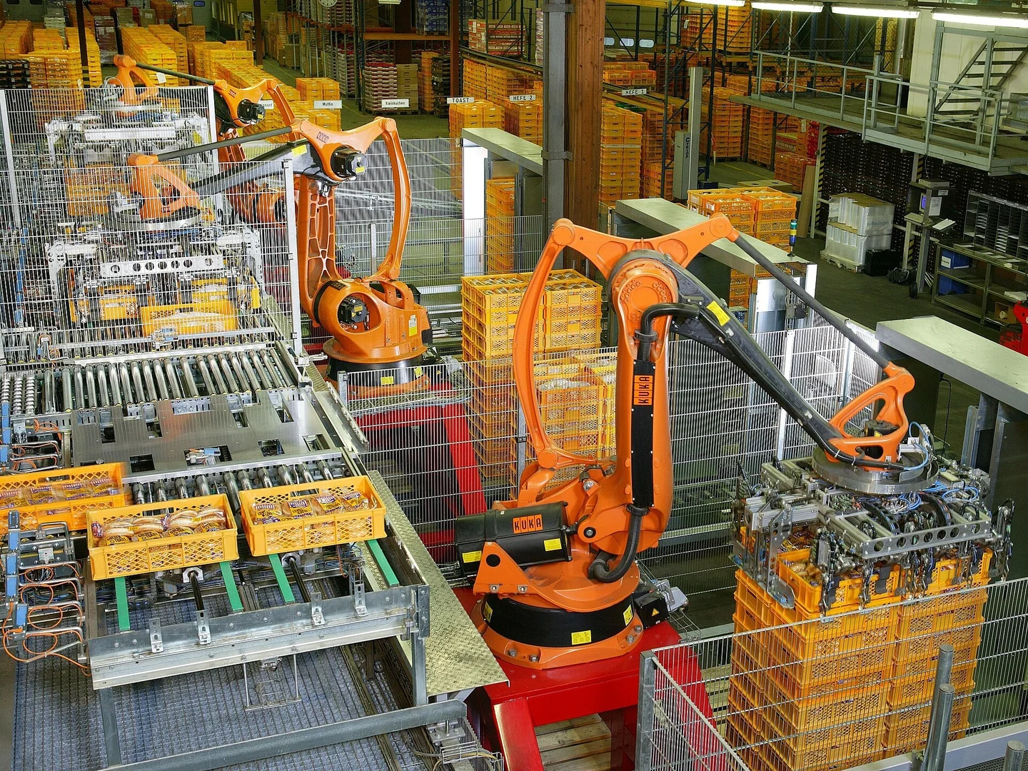
Industrial robots work in factories by turning a planned task into controlled movement. Sensors report the state of the workpiece and cell. A robot controller runs the motion program, servo drives power the motors, and a tool grips, welds, paints or handles the part. The cell then checks the result before the next cycle.
So, how do industrial robots work in factories when several machines share one line? The key is coordination. A robot may be ready to move while a clamp, conveyor or machine tool is not ready. This guide follows a handling cycle and shows what to record when that cycle stops.
What makes a complete robot work cell?
The arm is one part of the system. A cell also needs a controller, end-of-arm tooling, fixtures, process equipment and suitable safeguards.
A programmable logic controller, or PLC, often manages the sequence between machines. Some cells place more of that logic in the robot controller. The exact division depends on the design.
| Cell element | What it does during a cycle | Useful evidence when the cycle stops |
|---|---|---|
| Robot controller | Runs the selected program and plans motion | Program, step, mode and alarm text |
| Servo drive and motor | Move each joint using feedback | Affected axis, drive status and load conditions |
| Gripper or process tool | Acts on the workpiece | Grip confirmation, tool state or process alarm |
| Sensors and vision | Report part presence or measured position | Input state, image result and time |
| PLC and machine interface | Exchange requests and completion states | Signal names, sequence step and timeout |
| Safety system | Permits or stops operation under defined conditions | Stop category, device state and reset conditions |
Ordinary process signals and safety functions have different roles. A basic “part present” input is not a substitute for a safety-rated function. Use the cell documentation to identify which system controls each permission.
Follow one pick-and-place cycle
1. Confirm that the station is ready
The sequence checks the selected recipe, operating mode, robot readiness and workpiece state. A conveyor may place a part at a stop, while a sensor confirms its presence. These conditions are design-specific; there is no single start signal that fits every factory.
2. Locate the part and plan the approach
With fixed tooling, the robot may use taught positions in a work frame. A vision system can provide a measured offset if the application needs one. The controller combines the work frame, tool definition and target pose to plan a path within the robot's limits. Vision does not remove the need for calibration.
3. Move, grip and confirm
The arm reaches the approach point, moves to the pick position and commands the gripper. The sequence waits for the required confirmation before leaving. A gripper command shows what was requested; it does not prove the part was held. Pressure, vacuum or jaw-position checks depend on the tool.
4. Transfer, release and report completion
The robot moves through the planned path, confirms that the destination can accept the part, and releases it. Completion signals let the next machine proceed. If the receiving station is blocked, the robot may wait without any failed motor or drive. The waiting condition matters as much as the visible arm position.
How do industrial robotic arms work with servo feedback?
The controller converts a tool path into coordinated joint targets. Servo control compares commanded motion with feedback and adjusts motor output. Control loops may be divided between the robot controller and drives. Their implementation varies by manufacturer and generation.
Position feedback helps the system track motion, but it does not by itself prove that a finished part is correct. A loose tool, shifted fixture or wrong work frame can affect the process while the joints follow their commands. Inspect the full chain from joint motion to the workpiece.
For the difference between joint movement, tool coordinates and position errors, see robot arm motion and coordinate checks. That guide covers motion detail; this article follows the complete production sequence.
How do PLC and robot signals stay in step?
A handshake is an agreed exchange of states. One device can request a transfer, and the other confirms readiness. The robot then reports that it is busy. A completion state closes the exchange. Signal names and timing are defined by the integrator, not by a universal robot standard.
Good sequence logic also defines what happens after a timeout, emergency stop or power loss. If one side retains an old completion signal, the next cycle may not start as expected. Record both devices' states at the same time. Resetting everything first can erase the evidence needed to locate the mismatch.
Where does a stopped cycle point the investigation?
| Observed stage | First distinction to make | Record before changing parts |
|---|---|---|
| Robot never starts | Missing permission or robot fault? | PLC step, start request, readiness and alarms |
| Arm reaches the part but waits | Tool command or missing confirmation? | Output command, sensor response and tool supply |
| Stop occurs during motion | Motion fault, process stop or external stop? | Full alarm, axis, pose and preceding events |
| Motion completes but part is misplaced | Tool, fixture, frame or motion error? | Actual part position, tool condition and recent changes |
| Next station never starts | Transfer incomplete or handshake mismatch? | Request, busy, complete and receiving-state history |
These are diagnostic branches, not proof of a failed component. Follow the applicable isolation and recovery procedures before inspection. Do not bypass guards or force safety inputs to make a stalled cycle run.
What changes between welding, painting and palletizing?
The control pattern is similar, but the process evidence changes. Welding needs the robot path and welding equipment to agree on process readiness. Painting adds material delivery and booth conditions. Palletizing adds product arrival, grip state and the selected stacking pattern.
When a process fails, record whether motion failed too. A robot that follows the path while the process tool fails needs a different investigation from a drive alarm. The robotic arm components guide helps identify the parts involved. The manufacturing output guide explains how waiting time affects the whole cell.
What should you send before a repair assessment?
- Robot and controller model, serial number and software version where available.
- Exact alarm text, timestamps and the first event before the stop.
- Program step, operating mode, affected axis and workpiece state.
- Tool and machine-interface signals, with PLC and robot records from the same cycle.
- Recent changes to tooling, wiring, recipes, backups or frames.
Keep a backup before approved changes. For industrial robotic arm repair, this record helps separate a cell-sequence problem from a drive, cable, tool or controller fault. Contact Suntech with the equipment identity and symptoms to define the assessment scope.
Does the robot type change the factory cycle?
Articulated robots use rotary joints to reach around fixtures. Their shape may suggest a human arm, but each model has its own limits. Cartesian robots use linear axes; delta robots use linked arms for suitable pick-and-place tasks. These designs can all take part in the same request, move, confirm and complete sequence.
Collaborative robots also need a defined cell process. Sharing a workspace requires an assessment of the complete task, including the tool and workpiece. The robot label alone does not decide whether guards are needed. In food processing, for example, hygiene and product handling add requirements beyond the motion program.
Do factory robots need artificial intelligence?
Many robotic systems run taught programs and fixed decision rules. They do not need artificial intelligence to repeat a known task. AI may help with tasks such as recognizing varied parts, but its output still needs a defined interface to the cell controls. Keep the chosen part, confidence checks and accepted position with the cycle record when such a system is used.
How do speed and precision affect the sequence?
High speed does not guarantee a short production cycle. During material handling, the tool may need time to build vacuum or confirm that a part is secure. Record those waits separately from arm motion. Compare the same product and recipe when checking a changed program.
High precision also needs a stated measure. Repeatability describes returning to a pose under defined conditions; it is not the same as absolute accuracy against an external reference. A stable robot can still place a part incorrectly if the fixture or tool frame shifts.
On assembly lines, production lines and other manufacturing environments, exchange timing matters. Real time control means meeting the timing needs of the designed system, not simply sending data quickly. Check the actual bus configuration, signal update and timeout settings before blaming a slow handshake on the robot hardware.
Technical references
IFR's industrial robot definition and structures establish the equipment scope. KUKA's robot controller overview describes controller architecture and integration options. The example cycle and fault-record table above are general engineering guidance; the installed cell's manuals determine its actual signals and recovery procedure.