

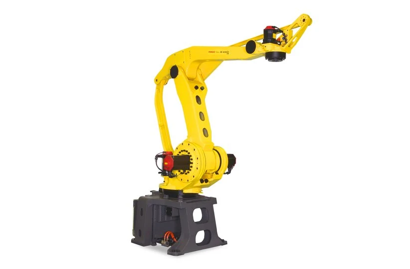
A robotic arm is a linked mechanism that moves a tool through a controlled workspace. Its controller coordinates joints, drives and feedback to place that tool where a task needs it. In a factory, the arm works with a gripper, welding torch or paint applicator, plus the equipment around the cell.
Understanding the structure helps when an arm stops, loses position or needs a replacement part. The same symptom can come from the tool, arm, controller or cell sequence. This guide explains the parts and types first, then shows how they affect maintenance and repair decisions.
What is the difference between a robot arm and a complete robot system?
The robot arm is the mechanical manipulator. A complete system also needs its controller, power and drive hardware, software, tool and protective equipment. A conveyor, fixture, vision system or PLC may coordinate the wider process. An arm alone does not define how the whole cell will work.
An industrial robotic arm is designed for specified operating conditions. Desktop teaching arms, research platforms and production robots may share a similar shape but use different motors, controllers and duty ratings. Identify the exact model before applying a maintenance method or comparing parts.
Robot arm components and what each part does
| Part or system | Role in the task | Useful information to record |
|---|---|---|
| Base, links and joints | Support and move the tool through its workspace. | Mounting position, axis number and collision history. |
| Servo motor, brake and transmission | Produce joint motion and, where fitted, hold a stopped axis. | Motor label, load, noise and when the symptom appears. |
| Encoder or other position feedback | Reports motion or position to the control system. | Complete alarm, affected axis and recent cable work. |
| Robot controller and drives | Execute the program and command the motors. | Controller identity, mode, software and full alarms. |
| Cables and connectors | Carry power, feedback and tool services. | Cable labels, routing and pose-related symptoms. |
| End effector | Grips a part or applies the process. | Tool mass, connections, fixture and process state. |
An end effector can fail while the arm still moves correctly. For example, a gripper may lose a part because its grip or vacuum is inadequate. That observation does not establish a robot positioning fault. Record the motion and tool events separately before choosing a repair route.
Types of robotic arms: structure changes the task
| Structure | Typical use | What to check for the actual model |
|---|---|---|
| Articulated | Reaching around fixtures for handling, welding or painting. | Joint limits, wrist orientation, tool load and cable routing. |
| SCARA | Planar assembly and pick-and-place with vertical travel. | Horizontal reach, vertical stroke and tool orientation. |
| Delta or parallel-link | Fast picking of suitable lightweight products. | Working envelope, moving tool mass and product tracking. |
| Cartesian or gantry | Linear travel across a rectangular workspace. | Axis strokes, mounting, cable carriers and alignment. |
These are structure categories, not guarantees of speed, load or accuracy. FANUC and KUKA list several robot families with different applications. Use a current model datasheet to confirm each limit; a familiar arm shape is not enough.
For manufacturer-specific context, read our FANUC robot classification article and compare its categories with the installed equipment.
How does a robotic arm complete a factory task?
- The cell checks its operating mode, protective conditions and equipment readiness.
- The controller runs the selected program using the recorded tool and workpiece frames.
- Drives command joint motion while feedback helps the controller track it.
- The end effector grips, welds, paints or performs another defined process.
- Cell signals confirm the next step, and inspection checks the process result.
A repeatable arm movement does not by itself prove a good product. Paint flow, welding conditions, gripper contact and fixture position can change the result. If the arm reaches the commanded pose but the work fails, keep the process evidence alongside the motion record.
Which specifications matter before replacing an arm or component?
Start with the task, tool and controller identity. A payload figure does not describe every allowed tool. Check the specified mass, centre of gravity and inertia conditions, including the gripper and workpiece. The load that the arm can handle depends on the model and its configuration.
Reach is also only one limit. The tool needs a usable path, orientation and clearance throughout the cycle. Review axis limits, mounting, nearby fixtures and cable movement. A target inside the maximum reach can still be unreachable with the required tool orientation.
Repeatability describes how closely repeated movements return under stated conditions. It is different from absolute positioning accuracy. Keep the terms separate when reviewing a datasheet, a calibration result or a production deviation.
- Record the full arm and controller models, serial numbers and software versions.
- Keep complete motor, drive, cable and tool labels, including suffixes and revisions.
- Check mechanical fit, electrical ratings, feedback and controller support together.
- Define backup, calibration and test requirements before a replacement is installed.
Matching connectors or a shared brand do not establish compatibility. Controller support, configuration and recovery steps also matter. Confirm those details against the applicable documentation before selecting a replacement.
Robot arm maintenance starts with a useful fault record
Follow the model manual for inspection and service intervals. In the maintenance record, keep the conditions that make a symptom repeat: axis, direction, pose, load, operating mode and elapsed run time. Note recent collisions, tool changes and work on cables or settings.
Separate a failure to start from an error during motion. If no axis moves, review controller and cell readiness. If one axis alarms or the fault follows a pose, preserve its first alarm and connected-circuit evidence. Neither pattern alone identifies a failed component.
Use the industrial robotic arm repair guide for component-level fault separation and repair records.
Questions to resolve before sending an arm or part for assessment
Does the whole arm need repair?
Not every stop requires arm disassembly. First identify whether the evidence concerns the cell sequence, tool, controller, cable or mechanical assembly. Share the observed behaviour and existing checks so the assessment can be scoped.
Can a replacement restore production without further setup?
That depends on the part and system. Some work affects configuration, mastering, calibration or tool data. Agree on the recovery procedure and test conditions in advance. A brief no-load movement does not verify the original production task.
For an assessment, use the contact page and send the equipment labels, full alarms, photos and the conditions that reproduce the fault.
Manufacturer references
Robot families and application context: FANUC robots by series.
Model families and specification filters: KUKA industrial robots.
Read more about motion and replacement
For joint, TCP and frame checks, read robot robotic arm motion.
Before an assembly change, use the arm for robot replacement checklist.