

A servo motor brake that will not release can stop an otherwise healthy axis. The fault may be a missing release command, lost supply, a broken brake wire or a mechanical problem inside the brake. Check the complete release circuit before ordering servo motor repair. A motor that hums or trips under load is not proof that its windings have failed.
This guide covers industrial motor holding-brake assessment, including motors used in robot systems. The exact motor suffix, brake option and controller determine the test method. First support gravity-loaded axes and secure the work area. Releasing a brake can allow movement even when the drive is not commanding motion; the machine procedure must define how the load is restrained.
1. Confirm that the fitted servo motor has a brake
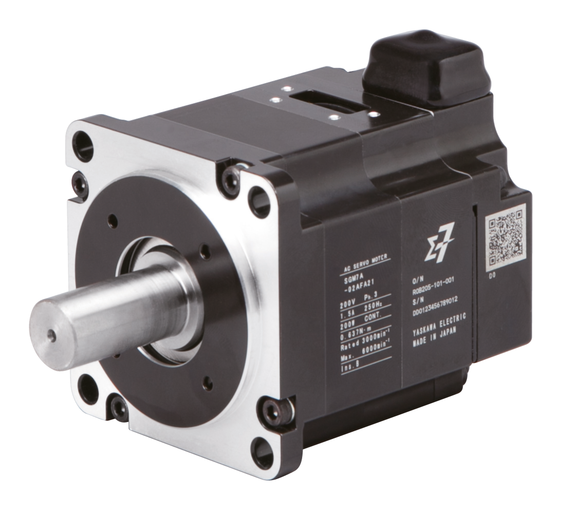
Read the complete motor label and original option code. Record the drive, controller, affected axis and any separate brake connector. A servo motor with brake can look like another version without that option. The Yaskawa SGM7A product listing, for example, includes different holding-brake options. Its option listing does not establish the wiring or test limits for an unknown installed motor.
Separate a motor holding brake from a dynamic-braking resistor, drive stopping function or external machine brake. They have different circuits and purposes. Check whether the reported issue is failure to release, failure to hold, slow engagement or drag during motion. This article follows the failure-to-release branch. A falling axis or failed holding test needs its own controlled assessment before any restart.
| Observation | Useful record | Diagnostic branch |
|---|---|---|
| Drive not ready | Enable state and first alarm | Controller sequence before the brake |
| Release commanded, no release | Command, supply and wiring identity | Output, cable, connector and brake circuit |
| Works cold, drags later | Duty, temperature location and timing | Supply stability and mechanical drag |
| Fault after replacement | Old/new suffix, connector and settings | Brake option and installation match |
2. Record the sequence before disconnecting anything
Save the first alarm, motor/drive labels and the exact point where movement stops. Record whether the drive becomes ready, whether a brake-release command is issued, and whether the fault began after a cable, relay or motor change. Photograph connector orientation and keep the approved parameters. Compare with the last known stable cycle, not an unrelated axis.
An encoder error, interlock or failed drive-ready condition may prevent brake release by design. Resolve that earlier condition through the controller procedure. Do not force the output just because the shaft does not turn. A brake click is useful evidence but does not prove that full release or holding performance is correct. Keep electrical and mechanical findings separate.
3. Inspect the isolated brake circuit
Isolate the machine, wait the specified discharge time and confirm the load restraint before cable work. Use the actual diagram to identify brake conductors, supply, switching device, protection and any suppression component. A motor power connector may carry several circuits. Never infer brake pins from the plug shape or test them as winding phases.
Inspect for recessed contacts, loose locks, corrosion, overheated terminals and damage at joint bends or cable clamps. With the circuit disconnected as specified, record continuity and any abnormal connection between conductors. If coil resistance is part of the approved test, compare it with the exact brake data at a recorded temperature. A finite resistance alone does not prove correct mechanical release.
4. Separate the command, supply and loaded voltage
A controller indication that release is requested does not confirm voltage at the brake. A qualified technician should use the specified adapter and procedure to trace command, switching and supply under the intended load. Compare source and endpoint conditions. A high-resistance contact may show a plausible unloaded reading but lose voltage when the brake is connected.
If the source is missing, assess the approved supply and output path before removing the motor. If the source is correct but the endpoint differs, investigate the intervening cable and contacts. If the specified endpoint conditions are met and the brake still does not release, assess the brake assembly. Do not apply an assumed external voltage, bridge contacts or defeat the machine’s release sequence.
5. Check for drag, misassembly and changed load
Where the electrical evidence is sound, inspect what changed mechanically. A damaged seal, contaminated friction area, distorted mounting or incorrect assembly can restrict motion. A bearing, reducer or coupled load may also resist movement after the brake releases. An approved isolated motor assessment helps distinguish motor drag from the installed mechanism without guessing from sound alone.
Do not force a supported robot joint or uncouple a vertical axis to see whether it frees up. Internal brake work requires the correct parts and assembly method. Some motor/brake units have restricted service options. Establish whether the model permits repair, a replacement brake assembly or complete motor replacement before opening the unit. Record the reason for that decision.
6. Repair the confirmed branch, then verify compatibility
A proven damaged harness calls for the specified conductor, contacts, sealing and routing correction. If a switching device is defective, match its electrical rating and the circuit’s suppression arrangement. Replacing a relay without checking the load and wiring may repeat the damage. Retain a record of the failed item and the evidence that isolated it.
For motor or brake replacement, match the full suffix, brake specification, feedback device, shaft and connectors. Preserve the encoder alignment and position information that the work may affect. Servo motor brake repair should include an agreed test scope; a shop must distinguish replacing a damaged part from verifying the complete motor and installed axis.
7. Verify release, holding and installed operation
Before power-up, recheck assembly, connector locking, cable restraint and the affected circuits. On the approved matched setup, record release and engagement behaviour, supply conditions, relevant alarms and the specified holding test. Use the manufacturer’s load and timing requirements. Do not substitute a hand feel or an unloaded spin for a holding-performance check.
After installation, verify the required position reference and the approved motion sequence with the load restrained as required. Then test the agreed payload and cycle, including repeated starts, stops and the original fault condition. Record current, temperature location, brake behaviour and alarms where measured. A brief alarm-free run does not establish operation over the full production duty.
Send the right information for servo motor repair
Provide the motor and drive labels, brake option, affected axis, first alarm and the failure-to-release sequence. Include connector photos, recent changes and any recorded source/endpoint checks. State whether the unit remains installed. These details help define whether the next step concerns the harness, supply, brake assembly or complete motor assessment.
Industrial servo motor repair assessment
Overheating: load, brake and feedback evidence
Encoder and feedback alarm repair
Manufacturer reference
The Yaskawa SGM7A page confirms that brake options vary within a motor family. It is used here for option identification, not as a universal brake-wiring manual. Obtain the installed motor and controller maintenance documents before testing. The checks above are a repair plan, not measured results from a completed customer job.