

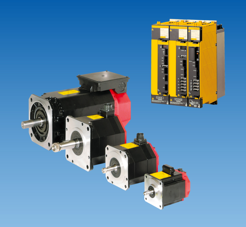
Servo motor repair for an encoder alarm starts by tracing the feedback path. The motor, encoder, cable and drive input form one system. A damaged connector or lost supply can produce a fault that looks like a failed encoder. Record the full alarm and its subcode before replacing parts. This plan explains how to separate those causes and define the repair test.
The method applies to repair assessment for industrial AC servo systems used with ABB, KUKA, FANUC and YASKAWA equipment. Pin assignments, feedback protocols, alignment and recovery steps depend on the exact unit. The YRC1000 alarm example below has a defined source; it is not a universal alarm number for other controllers.
Industrial servo motor repair and assessment
1. Capture the first encoder alarm and preserve position data
Record the motor and drive labels, controller version, affected axis, first alarm, subcode and event time. Note whether the fault began at power-up, servo enable, one joint position or after maintenance. Save the alarm history and the approved controller backup. Keep the existing parameter set and calibration records before changing hardware.
Distinguish a communication alarm from a low backup-battery alarm or lost absolute-position data. They may need different recovery work. Disconnecting an absolute encoder or removing its battery can affect stored position. Establish the model-specific data-retention procedure first. A successful reset does not prove that either the feedback path or position reference is sound.
| Observed fault | Evidence to collect | Next branch |
|---|---|---|
| At every power-up | Axis/subcode and recent wiring changes | Connector, supply and communication path |
| Only near one joint pose | Pose, direction and cable routing | Moving harness and connector strain |
| After a motor or encoder change | Old/new full labels and backups | Protocol, compatibility and alignment |
| Battery or position message | Exact alarm text and power-loss history | Battery circuit and position recovery |
2. Inspect the servo motor feedback cable and connectors
Isolate the machine and observe the controller discharge time before opening connectors. Support gravity-loaded axes using the machine procedure. Photograph cable labels and connector orientation. Check for bent or recessed contacts, oil or coolant, damaged seals, loose locking hardware and broken strain relief. Inspect robot-joint bend points and cabinet cable entries.
With both ends isolated as required by the wiring diagram, a technician can check conductor continuity, unintended connections and the specified shield path. Use the correct terminal map; a cable with the same plug may have a different pinout. Record each suspect circuit and its measurement conditions. Do not apply an insulation tester through the encoder, drive input or feedback electronics.
3. Separate supply loss from an encoder communication error
An encoder needs the correct supply and a sound signal path. With the approved test adapter and model-specific procedure, qualified personnel can compare supply behaviour at the source and feedback endpoint. A normal unloaded reading may fall when the circuit is connected. Separate a shorted harness, poor contact and overloaded supply before condemning the sensor.
Use the installed protocol to choose the signal test. Incremental channels, resolvers and serial absolute encoders do not share one waveform or test method. A continuity meter cannot validate serial data. Any powered measurement needs suitable isolation, probes and a documented connection point. Do not inject a generic pulse train or hot-plug a feedback connector to provoke the fault.
4. Use the alarm topology: YRC1000 code 1325 example
The Yaskawa YRC1000 Alarm Codes manual identifies 1325 as COMMUNICATION ERROR(ENCODER). In the multi-drop arrangement described there, a communication failure can also flag later encoders in the chain. Several reported axes therefore do not establish that several motors have failed. Follow the subcode and actual wiring order.
The manual directs checks around the first reported axis and the preceding encoder connection. Its listed branches include cables, multi-port connectors, encoder modules and controller-side hardware. This example concerns that YRC1000 arrangement only. Obtain the matching maintenance procedure before selecting connector pins, board variants or a replacement. A controller board is not the first conclusion from an encoder message.
5. Prove the suspect section before ordering servo motor encoder repair
Change one verified item at a time. A compatible, documented test cable can help isolate the harness; an approved bench setup can separate the motor feedback device from the installed drive. Record the exact substitution, retained settings and whether the same fault returns under the same condition. Similar-looking components are not suitable test substitutes.
If the fault persists with a verified harness and correct supply, assess the encoder and its internal connection. If an assessed motor works on a matched bench setup but fails in the machine, review the remaining installation and controller path. That result narrows the investigation; it does not by itself certify every controller input or production condition.
6. Repair the confirmed defect and preserve the motor match
For a proven cable fault, use the specified cable, contacts, shielding, sealing and bend arrangement. Replace damaged contacts or the harness rather than hiding a fatigue point inside a stiff splice. For contamination, determine how fluid entered and inspect corrosion; wiping the connector alone is not evidence that the defect has been removed.
Encoder replacement may require a specific device, mounting method, commutation alignment and position recovery. Preserve the complete motor suffix, brake option and feedback type. A repair shop must establish the alignment and matching test capability before opening that assembly. Do not turn an encoder body or rewrite offsets by trial and error to silence an alarm.
7. Verify feedback, then release the installed machine
Before power-up, check assembly, connectors, protective bonding and any disturbed circuits. On a matched bench, record feedback identification, stable position reading, approved rotation checks, direction, current and recurring alarms. Test the original failure condition where the setup can reproduce it. List the untested conditions in the report.
After installation, confirm the required position reference, tool path and affected axis before automatic running. Use the approved low-speed and safeguarded verification sequence, then the agreed production cycle. Check repeated power cycles, cable movement, alarm history and positional repeatability against the machine requirements. Record actual results; do not report a completed repair from one alarm-free reset.
Send the evidence for servo motor repair
Share the complete motor and drive labels, controller model, first alarm/subcode, fault timing and connector photos. State whether a cable, encoder or battery was disturbed and what backups exist. These details let us define the assessment, alignment needs and test scope before arranging servo motor encoder repair.
Servo motor overheating: load and brake checks
Industrial servo motor feedback and testing
Manufacturer reference
Technical reference: Yaskawa YRC1000 Alarm Codes, manual 178644-1CD, RE-CER-A600, major-alarm pages 325–326, code 1325. The cable-first branches above are an assessment plan; they are not recorded results from a customer repair.
Yaskawa official YRC1000 alarm manual listing
SGM7G-13APK Encoder Repair: YR1 and YR2 Matching
Position error after a FANUC motor change: reference, brake and frame checks