

Servo motor repair for overheating starts with the operating conditions, not a parts order. A hot motor can point to excess load, a brake that does not release, poor heat transfer or an electrical fault. Heat alone does not identify a failed winding or encoder. Keep the first alarm and the full motor label before arranging an assessment.
This guide covers industrial AC servo motor repair, including units used with ABB, KUKA, FANUC and YASKAWA equipment. It explains how to separate likely causes and agree a repair test. It does not give a universal temperature limit: housing temperature, winding temperature and the drive’s thermal estimate are different quantities. Use the limit for the exact motor and installation.
Industrial servo motor repair: assessment and enquiry
Record when servo motor overheating begins
Note whether the temperature rises while the axis holds position, during acceleration or after repeated cycles. Record ambient temperature, warm-up time, payload, speed, stops and the measurement location. Use the same instrument and method for a comparison. Shiny metal can affect an infrared reading, so a reading from one surface is not automatically comparable with another.
Keep the alarm text and event order. A thermal warning after a longer cycle needs a different review from a sudden fault immediately after a cable change. If there is smoke, a damaged connector or repeated protective trips, stop the test. Do not keep resetting the alarm to collect more production cycles.
Use the heat pattern to choose the next check
| Observed pattern | Useful evidence | Checks to discuss |
|---|---|---|
| Hot while holding still | Axis pose, payload and holding-current trend | Gravity load, brake sequence and mechanical balance |
| Hot after fast cycles | Cycle time, acceleration and current trace | Duty, load and thermal recovery |
| One connection is discoloured | Connector photos and prior cable work | Contact condition, cable damage and insulation |
| Heat follows maintenance | Before/after settings, alignment and load records | Assembly, configuration and changed external conditions |
Separate the mechanical load from motor damage
A motor may draw more current because a reducer, bearing, coupling or driven mechanism resists motion. Compare the same axis under the same approved task, rather than comparing unrelated robots. Look for a new load, changed tooling, tight cable routing or a recent collision. Keep noise and current records together so the technician can compare them.
Qualified personnel must isolate power and support gravity-loaded axes before mechanical work. Do not uncouple a vertical axis or force a shaft just to see whether it turns. Record the checks that were possible without disassembly, then agree any further inspection with the person responsible for the machine. A jammed load can damage a replacement motor too.
Check the brake sequence and heat-transfer path
An optional holding brake must match the motor and the controller’s release sequence. A brake that drags can raise the load, while a brake-control problem can resemble a motor fault. Inspect the evidence for the actual brake circuit using the approved documentation. Do not apply an assumed voltage or release a loaded brake without supporting the axis.
Review mounting, contamination and the surrounding heat sources. Oil, dust, a changed cover or a poor mounting interface can change cooling. Some motors rely on their specified mounting arrangement for heat transfer. Do not add a fan and call the fault repaired before checking why the temperature changed.
Compare current, duty cycle and feedback
Ask for the drive’s current and thermal history over a repeatable cycle. A brief peak and sustained current mean different things. Compare the trace with the motor/drive ratings and the applicable duty definition; a screenshot of one instantaneous value is not a complete load assessment. Leave any rating or limit unconfirmed until the correct manual is available.
Poor feedback, damaged feedback cables or unsuitable tuning can make the axis hunt or vibrate. Keep the encoder identity, connector condition and parameter-change history with the current record. An encoder alarm does not by itself justify servo motor encoder repair. The cable, power supply and drive feedback input may need separate checks.
What should electrical inspection establish?
Bench inspection should identify the winding, insulation, connectors, bearings, brake and feedback device that belong to that unit. A technician may compare winding resistance between phases and against the manufacturer’s method at a recorded temperature. A simple continuity check does not prove that every winding fault has been excluded.
Use only the specified insulation-test procedure. Feedback electronics, temperature sensors and the drive may need to be disconnected or protected before testing; applying a test voltage through them can cause damage. Record the test method, instrument and result. Do not treat a generic test voltage or resistance threshold as valid for every servo motor.
Repair the confirmed cause, then check the match
The repair quote should identify the confirmed defect and the proposed work. Bearing or seal replacement needs the correct fit and assembly method. Winding work must preserve the motor’s electrical specification. Encoder work may require alignment and a matching test setup. Cleaning alone is not proof that the cause of overheating has been removed.
If replacement is the better option, check the complete part number and suffix, feedback, brake, shaft, flange and connectors. A similar housing or power rating is not enough. Keep the old label and the machine records. Replacing the motor without correcting an external overload may reproduce the same fault.
Agree bench tests and the installed acceptance cycle
A bench report should state the drive and feedback setup, rotation and brake checks, current observations and limits of the test. Free running on a bench cannot reproduce every robot load. Separate a passed bench check from release of the complete machine.
For the installed test, use an agreed cycle and record payload, speed, ambient conditions, temperature location, current trend and alarms. Compare results over a sufficient warm-up period defined for the task. Record only measurements actually taken. A short run with no alarm does not prove that a thermal fault is resolved under production duty.
Send the right information for servo motor repair
Use the enquiry form below to share the brand, full motor and drive labels, affected axis and the conditions that cause heat. Add clear photos of connectors, mounting and visible damage. State whether the unit is still installed and what has changed recently. We can review the evidence and confirm the assessment scope, test needs and next step.
Servo motor feedback and fault-testing guide
YASKAWA robot no-motion checks
Manufacturer references
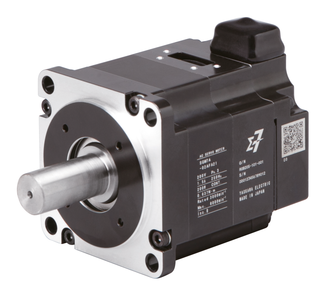
The Yaskawa SGM7A product reference shows why the exact feedback and brake option matter. It is an equipment example, not a claim that every industrial robot uses this motor. For a repair decision, obtain the manual and limits for the installed unit.
Yaskawa SGM7A motor options and product information