

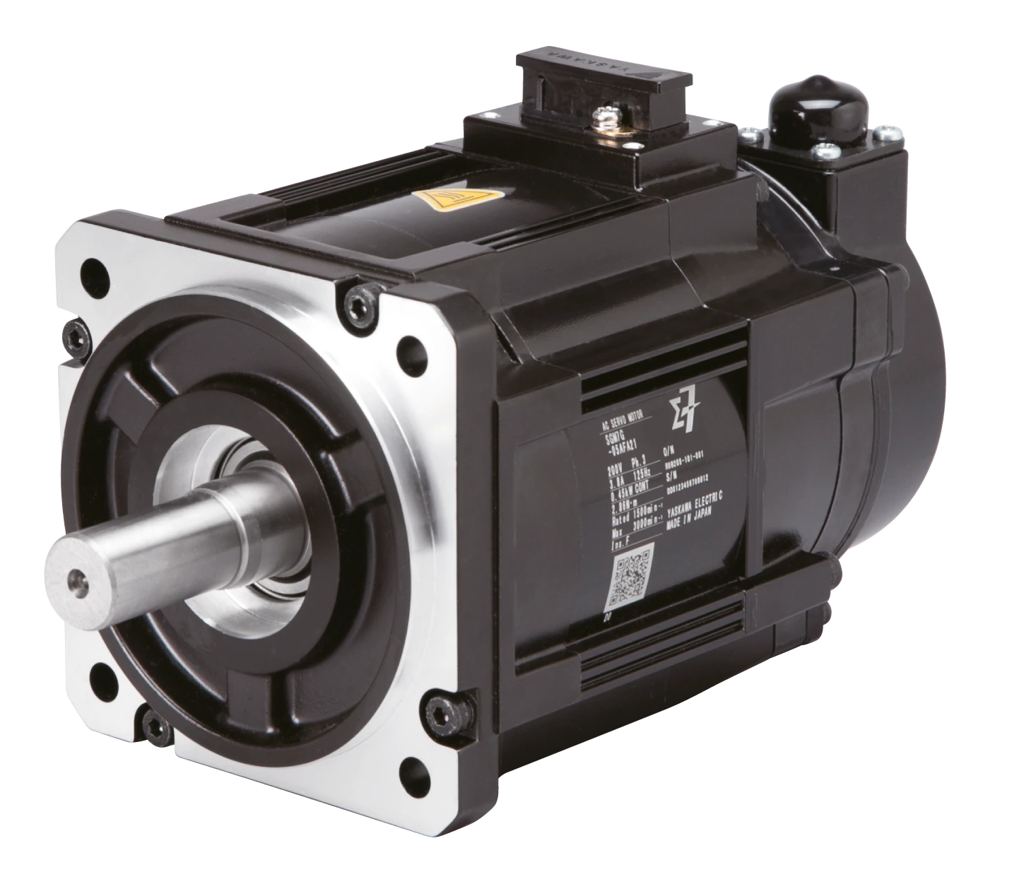
Yaskawa SGM7G-13APK encoder replacement requires more than matching the motor family name. The official replacement manual distinguishes SGM7G-13APK-YR1□ from SGM7G-13APK-YR2□ and lists different encoder branches. Read the complete motor and encoder labels before ordering a part. A similar plug, housing or nominal motor rating is not a compatibility check.
This guide concerns those robot-use motor variants listed in Yaskawa manual 185870-1CD, HW1485676. The square is a suffix placeholder; keep the actual final character from the installed label. Do not extend this procedure to an SGM7G-AFC variant or another motor simply because it carries the Sigma-7 family name.
1. Prove that encoder replacement is the right repair
Save the original alarm, controller identity, affected axis and event sequence. Distinguish communication interruption, battery/data-loss warning and confirmed feedback-device failure. Inspect the external feedback cable and documented supply path before dismantling the motor. The alarm alone does not establish an internal encoder defect.
For servo motor repair, agree what evidence supports replacement and what the setup can verify. Preserve the machine backup and valid position reference before changing the feedback assembly. A copied parameter file does not by itself preserve mechanical alignment or absolute-position validity. Record complete old/new component identities.
| Motor designation | Listed encoder branch | Check before ordering |
|---|---|---|
| SGM7G-13APK-YR1□ | UTTAH-B20RT / UTTAH-B20RT50 | Full suffix, encoder label and production-date note |
| SGM7G-13APK-YR2□ | UTTAH-B20RT30 | Full suffix and the separate replacement branch |
| Other SGM7G variants | Not established by this table | Obtain applicable motor and replacement instructions |
2. Match the encoder branch and supplied parts
The subject-motor table identifies UTTAH-B20RT and UTTAH-B20RT50 using a production-date distinction. Verify the actual encoder and current parts guidance rather than assuming a newer code is a universal substitute. The YR2 branch uses UTTAH-B20RT30 in the table and has separate removal and installation sections.
The manual lists different O-ring sizes: S75 for the RT/RT50 parts and S50 for RT30. Confirm the specified kit for the installed configuration. Reusing an apparently intact seal or fitting a ring from the other branch can defeat the intended assembly. Keep packaging labels and traceability with the motor record.
3. Prepare the motor and clean working area
The manual requires power off and encoder wires disconnected for this replacement work. The robot’s mechanical support and motor-removal requirements also apply where relevant. Establish the sequence from the installed system before opening the encoder end; a bench procedure does not justify releasing a loaded robot axis.
Remove dirt around the cover and use the specified clean, dry and static-controlled conditions. Protect the coupling, tapered surfaces and encoder from contamination and impact. The manual says not to loosen unspecified bolts or screws. Do not probe, scratch or force precision mating parts to accelerate removal.
4. Keep the Oldham coupling orientation identifiable
Use the removal section for the actual branch. Retain the orientation and identity of the Oldham hub, slide and encoder assembly. The manual identifies the encoder, O-ring and Oldham slide among replacement subjects; use the approved kit and condition assessment, not an assumed reuse rule.
Installation requires the triangle-shaped check marks on the Oldham hub and slide to align. The manual also directs retaining the supplied grease on specified coupling parts. Wiping it away or rotating parts until screws fit is not an alignment method. Confirm marks and clean mating surfaces before seating the unit.
5. Apply the specified mounting requirement only here
For the cited encoder mounting, the manual lists four M3 screws of 20 mm length and a tightening torque of 1.48 N·m. It describes the supplied adhesive arrangement. These values belong to this assembly, not every SGM7G fastener, motor mount or connector. Confirm the current matching kit and instruction revision.
Use an appropriate calibrated torque tool and preserve the intended washer, seal and mounting arrangement. Do not add unapproved adhesive or compensate for poor seating by tightening harder. A seated cover does not prove coupling marks remain correct. Record part numbers, alignment checks and fasteners so the assembly can be reviewed.
6. Restore feedback and position through the installed system
Restore the correct encoder connection and required backup arrangement using the documented circuit. The manual has different dimension and connector information for the branches; do not copy RT30 terminal information onto RT/RT50. Obtain the actual circuit before electrical checks.
Encoder replacement may require the robot’s prescribed position recovery or mastering procedure. That work is separate from clearing an alarm. A battery-only recovery function may explicitly exclude hardware replacement. Use the installed robot instructions and retained reference records; never invent an offset to make one point appear correct.
7. Verify the assembly before production duty
The replacement manual calls for checking alarms and abnormal noise in teach mode afterward. Confirm assembly, restraint and reference checks, then use the approved safeguarded sequence. Observe feedback identity, direction and the affected axis under defined conditions. Stop if behaviour differs from the expected system response.
Follow with required position and tool-path checks and agreed production acceptance. Record alarm status, motion observations and test limits. An encoder recognized on a matched bench is not proof that the installed robot is correctly mastered. Separate part replacement, motor test, position recovery and cell release in the report.
Send an SGM7G-13APK repair request
Send clear motor and encoder nameplates, the full YR suffix, controller/robot identities, alarm history and prior encoder work. Include available backups and installed-state details. Define the correct encoder branch, parts, alignment work and acceptance scope before scheduling replacement.
Feedback diagnosis before replacement
GP400 position checks after motor replacement
Manufacturer replacement manual
Reference: Encoder Replacement for AC Servomotor SGM7G Series, 185870-1CD, HW1485676, subject-motor table 1.2, parts/tools 1.3 and sections 2.1–2.4. Full suffix determines applicability. These are source-based repair checks, not measured results from a completed customer job.