

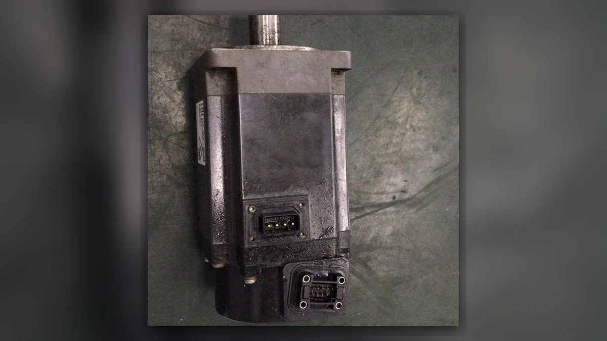
Servo motor repair after a ground fault starts by separating the motor winding from its power cable and drive. A damaged cable, wet connector or winding-to-frame fault can interrupt the same axis. The alarm alone does not identify the failed part. Keep the first alarm, axis and operating condition before resetting the system.
This guide follows the power circuit through isolation, inspection, measurement and repair acceptance. It addresses an electrical fault to the motor frame, rather than a loose protective-earth connection. Test methods and limits must come from the exact motor, cable and controller documents. There is no single insulation-test setting for every robot motor.
Industrial servo motor repair: inspection and assessment
1. Identify when the ground fault appears
Record the full robot, motor and drive part numbers, including suffixes. Save the first alarm, subcode and affected axis. Note whether it occurs at power-up, servo enable, acceleration or one joint pose. Ask about recent motor removal, cable work, washdown and liquid leaks. Keep photographs of the connectors before cleaning them.
| Fault timing | Inspect first | What it does not prove |
|---|---|---|
| At servo enable | Power connectors, cable and isolated motor circuit | That the drive or motor alone is defective |
| Only at one joint pose | Moving power harness, clamps and bend points | That every conductor passes under motion |
| After washdown or a leak | Seals, connector wells and the path of liquid | That drying the visible surface repairs the winding |
| After motor replacement | Full suffix, terminal map and cable seating | That matching plug shapes establish compatibility |
2. Isolate the cable and motor before testing
Stop the cell, isolate its energy sources and follow the controller discharge procedure. Support gravity-loaded axes before disturbing motor or brake connections. Verify the safe state using the approved method. Mark both ends of the power cable so that the repaired assembly can be traced to the original axis.
Use the wiring diagram to separate the drive output, motor power circuit, brake and feedback circuits. Built-in temperature sensors and other electronics may need separate protection. An insulation tester connected through a drive or encoder can damage it. Set the test points only after the circuit boundaries are confirmed.
3. Distinguish a power cable fault from winding damage
Inspect the entire accessible power path. Look for worn insulation at clamps, crushed sections, loose strain relief and heat-damaged contacts. Inspect connector inserts for conductive debris, moisture or tracking. Check the moving harness along its normal route; do not force it through a bend that it does not see in service.
With the cable disconnected at both ends, apply the cable-specific inspection and electrical test procedure. Compare each conductor with the other circuits and the shield or earth as the diagram requires. Record the instrument, test conditions and results. A continuity pass alone does not establish insulation condition or exclude an intermittent break.
Then assess the isolated motor power circuit using its approved procedure. Compare the winding-to-frame results with the motor-specific limits at the recorded temperature. A poor result confined to the motor side points to a different repair scope from a cable-side defect. If both sides pass, keep the intermittent-fault branch open rather than ordering a motor.
4. Read phase resistance alongside insulation results
Servo motor winding tests answer different questions. Phase-to-phase resistance can help identify an open circuit or imbalance. Winding-to-frame insulation checks assess leakage to the frame under the stated test conditions. Neither replaces the other. Record the winding connection and terminal pairs; do not invent separate phase results when the internal connection does not allow them.
Use a suitable low-resistance method where lead and contact resistance matter. Compare readings at a known temperature and with a valid reference or manufacturer limit. Balanced resistance does not exclude every turn-to-turn defect. Any further surge, high-voltage or powered test needs a motor-specific approved method and suitable equipment.
5. Use the YRC1000 alarm as a branch, not a parts list
The Yaskawa YRC1000 Alarm Codes manual lists ground faults and shorts in the U, V and W motor power circuit among the checks for alarm 1547 CURRENT FEEDBACK ERROR and alarm 1554 OVERCURRENT(SERVO2). The same entries also contain other causes. Their presence is a reason to investigate the circuit, not proof that a motor winding has failed.
For that controller, retain the subcode and installed hardware details when following the manual. Other controller generations use different alarm definitions. Keep the first event and later alarms in order. A fault at a shared connection may generate more than one message; counting messages is not a reliable way to count failed parts.
6. Match repair work to the confirmed defect
| Confirmed finding | Work to assess | Related check |
|---|---|---|
| Damaged cable or contact | Correct cable or connector repair/replacement | Terminal map, shielding, strain relief and flex route |
| Contamination at a connector | Approved cleaning or affected-part replacement | Liquid entry path and connector sealing |
| Motor insulation defect | Specialist winding assessment or motor replacement | Rotor/feedback assembly requirements and exact motor identity |
| No isolated defect reproduced | Document conditions and investigate the remaining path | Drive output, temperature and pose-dependent evidence |
Remove the cause of contamination as well as its residue. Inspect the source of coolant, oil or water and the sealing surfaces. Drying may change a reading without restoring damaged insulation. A winding repair must account for the motor construction, magnets and feedback alignment. Record any limitations before quoting repair or replacement.
7. Define the post-repair test and return-to-service record
Before power, check assembly, connectors, the protective-earth path and the required circuit results. Record the repaired part, instrument, method, temperature and acceptance limit. Use a compatible drive and the correct feedback arrangement for permitted bench tests. Do not reconnect an unverified assembly just to see whether the alarm resets.
An unloaded bench run does not prove the installed load cycle. After installation, agree the permitted motion, tool, load and duration. Observe alarms, current, temperature trend and the original failure condition where a controlled test allows it. List any untested condition. Keep bench evidence separate from the cell acceptance record.
Further repair guides and manufacturer reference
Encoder and feedback alarm diagnosis
Servo motor overheating: compare load, brake and feedback
Yaskawa YRC1000 Alarm Codes: 1547 and 1554, PDF pages 364–365
For a repair assessment, send the complete labels, first alarm, fault timing and any separated cable/motor results. State whether the unit has been opened and whether liquid entered it. These records help define the next check and which acceptance tests can actually be performed.