

YASKAWA robots that do not move need a sequence check before a part is removed. Confirm whether the controller accepts servo enable, whether motion works in the approved manual mode, and where an automatic cycle stops. A missing start condition can look like a failed motor. Save the first alarm and the controller state before resetting anything.
This guide concerns industrial MOTOMAN systems and repair assessment. It separates control conditions, cell signals and component faults. The installed controller, robot, options and safety design determine the actual procedure. Use their manuals; a generic alarm list or a similar-looking cabinet does not establish a diagnosis.
YASKAWA MOTOMAN robot repair and related guides
Identify the YASKAWA robot and controller first
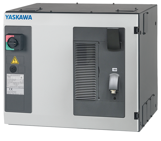
Record the arm model, serial label, controller type and complete alarm text. Include the affected axis or group, selected job and whether the problem follows a shutdown, cable change or collision. DX100, DX200, YRC1000 and YRC1000micro are controller names, not interchangeable wiring or parameter instructions. Keep the actual options with the record.
Separate the arm label from motor, drive and pendant numbers. Send a clear cabinet photo and close views of the relevant labels. Record which unit remains installed. These details help the repair team choose the correct documents and decide whether the next step is a signal review, a cable inspection or component testing.
Find the first point where the motion sequence fails
| Observed state | Record next | Do not assume |
|---|---|---|
| Controller not ready | First message, supply history and controller identity | The servo motor has failed |
| Servo enable not accepted | Mode, safety state and required enable conditions | A safety input should be bypassed |
| Manual motion works; cycle will not start | Selected job and PLC start/ready sequence | The drive is defective |
| Fault appears at one pose or under load | Axis, pose, load and first alarm | The named part is the only cause |
Servo enable is a condition, not a parts diagnosis
Record the displayed operating mode, stop state and enable status using the approved operator procedure. The cell may require several conditions before the controller permits motion. Read status information rather than bridging a guard circuit or forcing a signal. A cleared message does not mean that the cell is ready for production.
If the servo-on request is rejected, preserve the first event and the related state. Follow the model-specific troubleshooting instructions. A fault may involve external interlocks, the power stage, feedback or another configured condition. Do not use a motor replacement to test an unexplained safety or enable fault.
If manual motion works, review the PLC handshake
When approved manual motion is possible but an automatic job does not start, compare the job selection and start sequence. Record the relevant PLC and robot I/O states at the same time: requested job, ready state, start request and acknowledgement where used. Signal names and polarity vary by cell; confirm them against the actual I/O map.
A start pulse at the PLC does not prove that the robot received or accepted it. Check the sequence and timing with the responsible controls engineer. A stale completion bit, missing fixture confirmation or wrong job selection can stop a cycle without a failed motor. Do not force outputs or modify the ladder just to get motion.
One axis fails: compare cables, feedback and load
A YASKAWA servo alarm needs the complete code, text, affected group and event order. Note whether it appears at enable, first movement or a repeatable pose. Cable-flex faults may change with position, but that pattern is a clue rather than proof. Keep recent connector work, liquid ingress and collision history in the review.
After the approved isolation procedure, qualified personnel can inspect accessible connector seating, damaged jackets and contamination. Do not probe a live connector or swap motor/feedback leads between axes. Wrong connections or changed feedback alignment can create a new fault. Mechanical binding, brake control, a motor defect and a drive defect need distinct evidence.
A dark pendant does not identify a controller failure
If the teach pendant is dark, record whether the controller is powered and whether other status indicators are present. Photograph the pendant and cable labels and note any drop or crush damage. A display, cable, supply or communication problem may require a different test setup. Avoid pulling connectors with power applied.
For a visible pendant with a stopped job, keep the actual screen message. A paused job, an active wait instruction and a communication alarm are different states. Send the job position and relevant status to the engineer. Restarting from another line without understanding the cell sequence may lose the workpiece or fixture state.
Decide which component should be assessed for repair
Prepare a fault record before removing a motor, drive, board or pendant. State which external causes were checked and what each check established. Our team can review YASKAWA robot repair enquiries using the full identity and fault evidence. A quotation should distinguish diagnosis, proposed component work and the tests that the available equipment can support.
Repair is not always the same as replacement. A replacement unit needs its full suffix, interface and options checked. Some work also needs backups, parameters or a model-specific recovery procedure. Do not erase data to clear a message. Preserve the existing records and agree who is responsible for installed setup.
Verify the repair and the complete production sequence
A component bench test may verify power, communication, feedback or controlled rotation with compatible equipment. It cannot prove that every cell interlock or application cycle is correct. The repair report should identify the unit, setup, observations and any test that was not possible.
On the installed system, confirm the approved recovery steps, fault status, I/O sequence and a controlled trial before normal production. The responsible team must validate safety functions and process conditions. Record the payload, speed, repeat cycles and alarms actually observed; do not invent a pass count or claim full-load testing from an unloaded run.
Send a useful enquiry about YASKAWA robots
Use the form below for the arm and controller models, first alarm, affected axis and point where the sequence stops. Attach label photos and permitted screen or signal records. Tell us whether manual motion is possible and what changed before the fault. We will confirm the next assessment step and test scope from the available information.
YASKAWA robot noise and vibration: what to record
MH180 grounding and cable fault checks
Servo motor repair for overheating
Use the manufacturer documents for the installed system
Yaskawa Motoman’s documentation library lists controller instructions, operator manuals and concurrent I/O material separately. Match the document to the controller and application. The general sequence in this guide does not replace those model-specific instructions or certify a repaired cell.
Yaskawa Motoman product documentation library
Yaskawa manufacturer support resources