

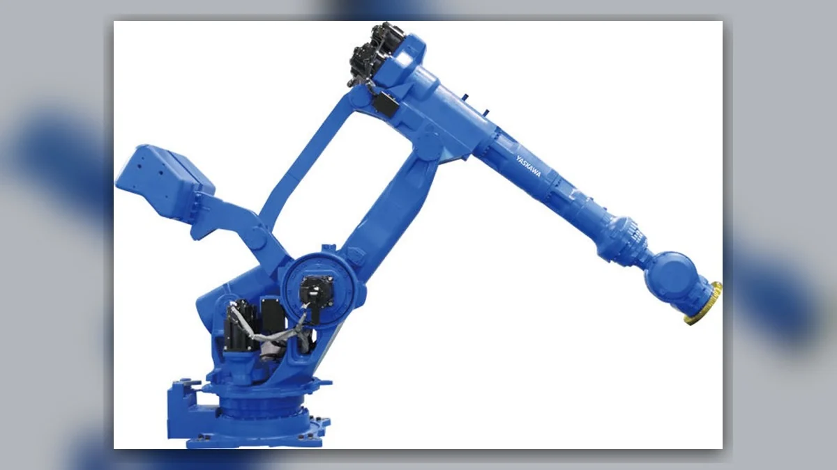
YASKAWA GP400 repair after a motor change may be followed by a position error even when the replacement motor runs. First distinguish an incorrect home reference, a tool/frame issue and a mechanical assembly problem. Do not move every taught point to hide the shift. Preserve the original job, tool data and home-position records so the changed relationship can be identified.
The cited manual is MOTOMAN-GP400, GP600 Maintenance, 184377-1CD, HW1484410, for the specified YR-1-06VX400 variants and YRC1000 documentation. GP400R and GP400L have different manuals. Verify the full arm type, controller and replaced motor before selecting a return-to-home method.
1. Record what changed and how the error appears
Identify the axis, full old/new motor labels, encoder identity and any disturbed coupling or reducer. Save backups and original home-position data before further adjustments. Record whether the difference is visible at a known reference, only at the tool tip, or only with a particular job/frame. Keep the replacement date and work sequence with the record.
A repeatable offset after maintenance is evidence to investigate, not proof that the reducer has failed. Variable error under load suggests a different branch from a stable reference shift. Keep tool number, payload, frame and measurement setup constant. Do not compare unrelated production points as if they were a calibration test.
| Observation | Evidence to check | Do not assume |
|---|---|---|
| Stable axis-reference shift | Home records and motor/encoder change | Every job point needs rewriting |
| Tool-tip error with axis references intact | Tool, flange and frame records | The robot home is wrong |
| Error varies with direction/load | Mounting, coupling and mechanical checks | Calibration alone will repair wear |
| Battery loss without hardware replacement | Backup state and matching recovery method | The same method works after an encoder change |
2. Check motor compatibility and the completed assembly
Match the full motor suffix, feedback device, brake option, connectors and fitted axis against the robot parts information. Preserve the supplier identification and actual work record. A matching power rating or bolt pattern is not sufficient. Confirm any mating parts disturbed during the motor replacement.
Inspect the relevant mounting, cable restraints, connectors and assembly records before powered testing. GP400 has a balancer-linked mechanism with model-specific restraints for L-axis work. The manual requires its specified fixing procedure when L-axis holding power is released. A generic sling or another robot’s posture is not a substitute for that procedure.
3. Select a home-position method for the actual event
Chapter 3.2 distinguishes a prepared teaching reference, a key-position method, an encoder-backup recovery function and robot calibration. They serve different events. For a motor or encoder replacement, check what valid reference was established before the change and what the fitted system permits. A recovery menu does not prove its method applies.
The manual states that the encoder backup error recovery function cannot be used when the motor or absolute encoder is replaced. This is a key distinction from a battery-run-out event. Do not use that function to skip the replacement-related home procedure. If reference records are missing, obtain the appropriate calibration support rather than inventing pulse values.
4. Use prepared reference and key records correctly
A teaching point for home-position adjustment must have been established under normal operating conditions before the replacement. Check that it belongs to the same robot and configuration. Do not teach the current shifted pose and call it the original reference. Keep the measuring method and physical reference identifiable.
For the key method, the manual describes the recorded difference between the key position and factory home pulse values. Key alignment without that relationship is not automatically the factory home. Verify the available label/record and follow the full method. A backup filename or values from a similar GP400 are not acceptable substitutes.
5. Separate robot reference from tool and frame errors
After the required home-position work, compare the affected reference under the prescribed conditions. If axis references are correct but the tool tip remains shifted, review the actual flange mounting, tool identity, tool data and user frame. A disturbed gripper or fixture can change the production result while the robot reference is intact.
Keep one factor fixed at a time. Record before/after observations and the selected coordinate system. Do not change tool data and home pulse values together before the discrepancy is understood. A compensating adjustment may make one location look right while increasing error elsewhere in the work envelope.
6. Escalate to the correct calibration branch when needed
The GP400 manual identifies robot calibration as an option when its preceding methods are unavailable. This requires specified measurements and setup, not approximate jog moves. Identify equipment, reference conditions and appropriate support before starting. Define whether the issue concerns one disturbed axis or the complete calibration relationship.
If checks instead reveal loose assembly, damaged mating parts or mechanical resistance, correct that defect before evaluating calibration. A coordinate change cannot repair backlash or a damaged component. Retain the findings and distinguish mechanical work from reference restoration in the repair report.
7. Verify more than one production point
After assembly and reference checks, follow the approved safeguarded verification sequence with clear travel and required test conditions. Check the original reference and representative locations and orientations affected by the work. Record the actual method and observations instead of promising a universal positioning tolerance.
Then verify the agreed tool, frame, payload and job. Confirm approach and retreat clearance as well as the working point. Separate reference recovery from production acceptance, and list any untested region or condition. Do not release the cell solely because one taught point can be reached without an alarm.
Prepare a GP400 repair assessment
Send arm/controller labels, changed axis, old/new motor and encoder labels, backup availability and original reference records. Explain whether the shift is constant, load-dependent or limited to a tool/frame. These details help define the YASKAWA GP400 repair, assembly check or calibration scope.
YASKAWA robot repair and model guides
YRC1000 battery alarms: distinguish lost data
Official model source
Reference: GP400, GP600 Maintenance Manual 184377-1CD, HW1484410, chapter 3.2 and table 3-1, plus chapter 4 L-axis fixing requirements. The recovery-method limits apply to the cited configuration. Actual parts and calibration work require the complete installed-system instructions.