

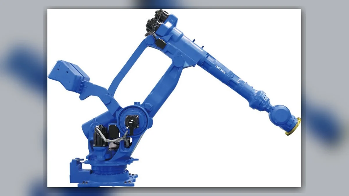
YASKAWA robots with alarm 4315 need a cause check before a restart. For the YRC1000 controller, the official alarm manual names this message COLLISION DETECT. It can involve contact, load or motion settings, wiring and drive components. The code alone does not prove that the robot arm or motor is damaged. This repair plan separates those branches and defines the evidence needed for release.
This article concerns YRC1000 alarm 4315. Match the controller, software, robot and alarm subcode to the installed manuals. Do not assume that a code on a DX100, DX200, YRC1000micro or another controller has the same recovery sequence. Preserve the tool, payload, job and backup before any adjustment.
YASKAWA robots: repair and fault guides
1. Capture the stop, axis and exact motion segment
Record the full message, subcode, affected axis/group, job name and line. Save the commanded direction, tool number, payload, speed and whether the robot was starting, braking or already in motion. Record fixture state and recent tool, cable, program or workpiece changes. An alarm screenshot without the motion context is incomplete.
Keep photos of any witness mark, displaced part or stretched hose. Save the alarm history and a controller backup using the approved procedure, including CMOS.BIN where applicable. Do not clear the evidence by repeatedly restarting the same segment. Inspection and controlled testing should proceed under the cell’s isolation and recovery procedure.
| Condition | Useful observation | Work branch |
|---|---|---|
| Contact with fixture or workpiece | Marks, shifted part, job position | Remove interference and inspect damage |
| No visible contact after a tool change | Tool number, mass and centre of gravity | Verify installed tool and load data |
| Alarm at starts or stops | Segment, direction and stop history | Review motion/load conditions |
| Alarm follows one axis or pose | Cable route, brake and current evidence | Inspect harness, motor and mechanical load |
2. Check for real contact before changing settings
With the cell secured, compare the stopped pose with the fixture, workpiece, gripper, torch and nearby equipment. Look for a loose workpiece, incorrect nest position, displaced locator or tool change. Check the full swept path, not just the robot flange. A hosepack or cable snag can apply force without leaving a clear metal impact mark.
Remove the confirmed obstruction and restore the documented fixture or tool condition. After an impact, inspect mounting, tool alignment, cable restraints and the affected mechanical assembly before movement. Keep damaged parts for assessment. An alarm reset does not establish that alignment, reducer condition or the next motion is acceptable.
3. Verify the active tool, payload and program
Check the active tool number against the tool physically fitted. Compare its mass, centre-of-gravity data and any inertia settings required by the installed system. Include the carried workpiece and gripper state. Review what changed since the last stable cycle; do not copy settings from a similar robot or use the arm’s headline payload as the tool value.
The YRC1000 manual lists tool information, job, speed and ACC/DEC among the setting checks for 4315. A programmer should compare the actual failing segment with the approved job and load data. Keep a before/after record for each correction. Do not disable collision detection or raise a threshold just to suppress the symptom.
4. Separate motion-load effects from a component defect
Determine whether the stop follows a collision, a HOLD/category-1 stop or a specific acceleration segment. The official manual describes an excessive-load branch involving the start/end pose and stopping conditions. This is a reason to review the actual trajectory and load with the integrator; it is not proof that every occurrence needs new servo hardware.
If a controlled test is approved, change one documented condition at a time and compare the same segment. Use the prescribed safe test mode and clearance. A fault that disappears at lower speed may still involve drag, load or wiring; lower speed alone is not a repair verdict. Record current/load traces where the installed controller supports them.
5. Inspect motor power and brake wiring
For a repeat fault without interference, isolate power and secure gravity-loaded axes before cable work. Check the affected axis’s motor power wiring, U/V/W connections, brake circuit, connector seating and cable bend points. Look for heat damage, corrosion, recessed contacts, damaged insulation and strain. Use the exact drawing to identify each circuit.
The YRC1000 4315 entry includes disconnected motor power phases and brake wiring as diagnostic branches. Test isolated circuits using the specified method, rather than opening a loaded brake or probing an assumed pin. Keep feedback electronics protected during insulation checks. Cabinet board connector names in the manual are configuration-specific; match the fitted board and revision before touching them.
6. Choose repair work from the findings
A proven broken power or brake wire calls for the specified harness/contact repair and routing correction. A brake that does not release needs its supply, wiring and mechanical condition separated. For a suspected motor or amplifier, use an approved matched assessment setup; the alarm alone is not a parts order. Record the unit identity and measured finding behind the recommendation.
If external wiring and settings are sound, review resistance to motion, abnormal noise, backlash and reducer condition through the manufacturer’s maintenance method. The manual includes reducer wear and mechanical maintenance among the branches. Internal reducer work needs the correct model procedure, parts and assembly checks. Preserve the backup before any controller-board replacement.
7. Verify the repair and restore the cell in stages
Before power-up, check assembly, fixed cables, connectors, protective bonding and any disturbed circuits. Confirm the approved job, tool and payload data. After the prescribed reset, verify the affected axis and clearance in the approved safeguarded test sequence. Follow the controller procedure for any position, calibration or tool checks required by the work performed.
Then verify the original segment with the agreed workpiece, load, speed and warm-up conditions. Record alarm history, current/load behaviour, cable movement and actual mechanical observations. Check both the repaired condition and the normal automatic sequence. State which tests were completed and which remain open; one successful empty cycle is not acceptance of full production duty.
Arrange YASKAWA robot repair with the right evidence
Send the robot/controller labels, alarm 4315 and subcode, affected job line, tool/load data, recent changes and clear photos. State whether there was contact and which isolation or tests have already been completed. We can use that evidence to define a YASKAWA robot repair assessment and agree whether a harness, motor, drive or mechanical inspection is needed.
YASKAWA robots not moving: enable and I/O checks
Servo motor encoder and feedback alarm repair
Manufacturer reference and controller scope
Source: Yaskawa YRC1000 Alarm Codes, 178644-1CD, RE-CER-A600, minor-alarm pages 272–273, code 4315. The manual includes mechanical, setting, cable and component branches. The steps here organise an assessment and verification plan; no customer measurements or completed repair results are claimed.